Fig.6, Fig.3 fig.5 fig.4 regulator, Fig.7 – Sealey SAC3203B3PH User Manual
Page 3: 5° max 5° max
A
C
Drain plug
B
fig.6
Breather (at rear)
A
Chocks
Fully
inflated
1.5bar
1000mm
nominal
Wall
Axle bolt
Spacers
Plain washer.
Plain washer/
spring washer/
spacer.
Receiver leg
Spring washer/
nut
Wheel
Receiver leg
Swivel castor
Nut/spring
washer
Bolt
5.3.
STARTING THE COMPRESSOR.
5.3.1. Your compressor is fitted with two push buttons for on/off switching. To turn the compressor on push the green "on" button. To turn the
compressor off push the red "off" button. (See fig.8)
5.3.2. Check that the on/off switch is in the “off” position.
5.3.3. Plug the mains lead into mains supply and start the compressor by pushing the green "on" button (fig.8) downwards.
5.3.4. Leave the compressor running with no air line or tools connected. Make sure that the pressure in the tank rises and that the
compressor stops automatically when the maximum pressure is reached. This value is written on the specification plate and may
take in excess of 5 minutes.The compressor will now operate automatically. The pressure switch (fig.8) stops the motor when the
maximum tank pressure is reached and restarts it when pressure falls below the minimum threshold approximately 2bar (29psi) less
than the maximum pressure.
5.3.5. Stop the compressor by pushing the red "off" button (fig.8) downwards. The compressed air inside the compressor head will flow out via
the air line tube situated beneath the switch housing. Restart is made easier and prevents the motor from being damaged.
DO NOT,
other than in an emergency, stop the compressor by switching off the mains power, or by pulling the plug out, as the pressure relief
will not then occur and motor damage may result upon restart. When the compressor runs correctly and is stopped correctly there will
be:
(a) A whistle of compressed air when the motor stops,
(b) A protracted whistle (about 20-25 seconds) when the compressor starts with no pressure in the tank.
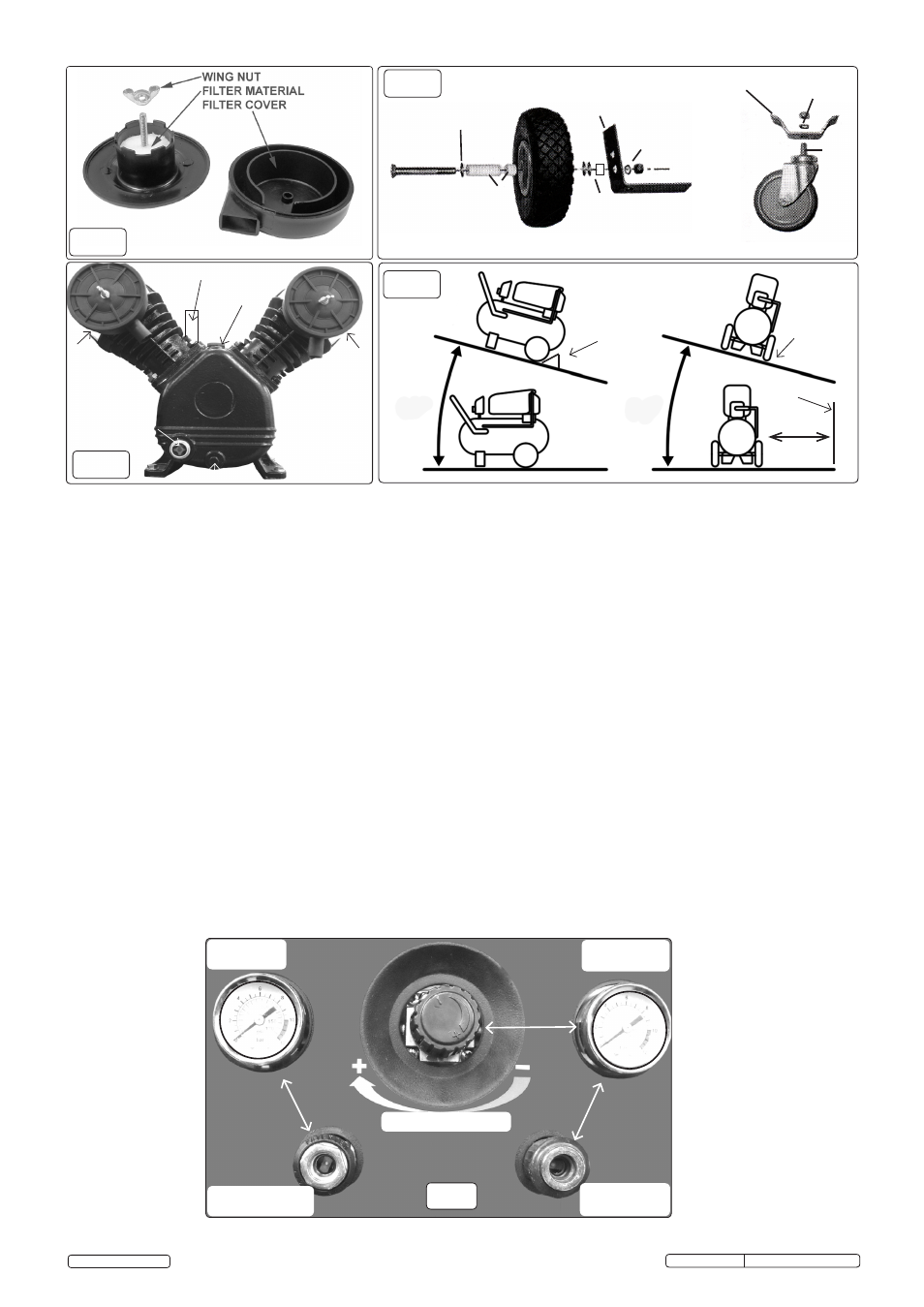
5.3.6. The output pressure is regulated by the pressure regulator (fig.7). Turn the knob clockwise to increase pressure and anti-clockwise
to reduce it. The knob can be locked at any required setting by tightening the locking ring against the underside of the knob. The
required pressure is determined by the pneumatic appliance user manual. When the compressor is not being used, set the regulated
pressure to zero, hence avoiding damage to the pressure reducer.
5.3.7. Two quick release supply sockets offer either full receiver pressure or a regulated supply pressure up to a maximum of the receiver
pressure. A third option 1/4"BSP female connection is via the receiver ball valve (fig.1) with unregulated pressure.
NOTE: If the motor does not cut in and out, but runs continuously when using an air appliance, the capacity of the compressor may be
too small for the equipment or tool. Should the pressure in the main tank exceed the pressure switch pre-set pressure maximum, the safety
valve (fig.8) will activate.
WARNING! DO NOT tamper with, or adjust, the pressure switch or safety pressure relief valve.
Original Language Version
SAC3203B3PH Issue No: 1 - 27/10/14
© Jack Sealey Limited
5°
max
5°
max
fig.3
fig.5
fig.4
REGULATOR
REGULATED
PRESSURE
RECEIVER
PRESSURE
REGULATED
SUPPLY
UNREGULATED
SUPPLY
fig.7
Control Panel
Gauges
PUMP