Introduction & specification, Preparation, Operation – Sealey SAC00015 User Manual
Page 2
2. INTRODUCTION & SPECIFICATION
Ideal for use where an oil-free air delivery is required and especially suited to small low pressure, touch-up and airbrush spraying applications
as well as general-purpose applications. Simple construction with fewer components makes these units practically maintenance-free. Reduced
weight gives greater portability. SAC00615 and SAC02415 supplied with a precision welded receiver tank, manufactured to meet Pressure
Vessel Directive 87/404/EEC, fully automatic pressure cut-out switch and air regulator with gauges. SAC02415 supplied with wheels and
handle. Fitted with ASTA/BS approved non-rewirable plug.
3. PREPARATION
3.1.
Remove compressor from packaging and inspect for any shortages or damage. If anything is found to be missing or damaged, contact
your supplier.
3.2.
If wheels and/or feet are not fitted to compressor, fit them using the appropriate nuts, bolts and washers supplied.
3.3.
Confirm that the mains voltage corresponds with the voltage shown on the compressor data plate.
4. OPERATION
WARNING! Ensure that you have read, understood and apply Section 1 safety instructions.
4.1.
The compressor should be located and operated in a position that allows good air circulation around the unit. locate the compressor
in a convenient position for the work to be undertaken. Ensure that it is standing on a stable and level surface. Ensure the feet/wheels
are in direct contact with the surface.
4.2.
Attach the required air tool to the air outlet.
4.3.
Plug the mains plug into a mains electrical socket, but do not switch the compressor on until the workpiece and air tool are fully
prepared.
4.4.
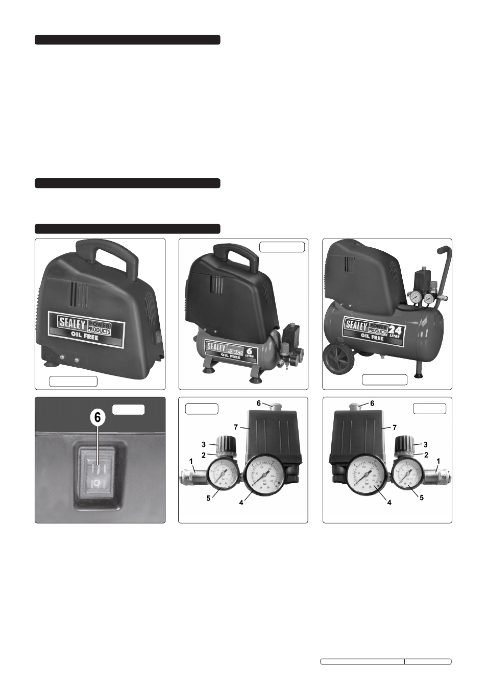
Switch on the unit by pushing the switch to the on position (SAC00015 - Fig.1.6) or pulling the red on/off switch upwards (Figs.2.6 &
3.6).
4.5.
on the SAC00615 and SAC02415 models, the output pressure is regulated by the pressure regulator tap (Figs.2.3 & 3.3). Adjust the
pressure regulator tap to the pressure required. The tap can then be locked at the required setting by tightening the locking ring
(Figs.2.2 & 3.2) behind the tap. When the compressor is not being used, set the regulated pressure to zero so as to avoid damaging
the pressure reducer.
NOTE: a) on the SAC00615 and SAC02415 models, if the motor does not cut in and out, but runs continuously when using an air appliance,
the capacity of the compressor may be too small for the tool being used.
SPECIFICATIonS:
Model No.: . . . . . . . . . . . . . . . . SAC00015 . . . . . . . .SAC00615 . . . . . . . SAC02415
motor output: . . . . . . . . . . . . . . . . . . 1.5hp . . . . . . . . . . . . 1.5hp . . . . . . . . . . . .1.5hp
Voltage/Phase: . . . . . . . . . . . . . 230V - 1ph . . . . . . . 230V - 1ph . . . . . . . 230V - 1ph
Input Current: . . . . . . . . . . . . . . . . . . . . .5A. . . . . . . . . . . . . . 5A . . . . . . . . . . . . . . 5A
noise level: . . . . . . . . . . . . . . . . . . 97dB.A. . . . . . . . . . .97dB.A . . . . . . . . . . 97dB.A
Air Displacement: . . . . . . . . . . . . . 6.35cfm . . . . . . . . . . 6.35cfm . . . . . . . . . .6.35cfm
maximum Free Air Delivery: . . . . . . 4.7cfm . . . . . . . . . . . 4.7cfm . . . . . . . . . . .4.7cfm
Tank Capacity: . . . . . . . . . . . . . . . . . . . n/a . . . . . . . . . . . . . . 6ltr . . . . . . . . . . . . .24ltr
maximum Pressure: . . . . . . . . 116psi/8bar . . . . . . . 116psi/8bar . . . . . . .116psi/8bar
overall Size (WxDxH): . . 340x180x360mm . . .480x180x490mm . . 570x300x600mm
SAC00015
SAC00615
SAC02415
Fig.1
Fig.2
Fig.3
Original Language Version
SAC00015, SAC00615, SAC02415 Issue: 2 - 20/02/12