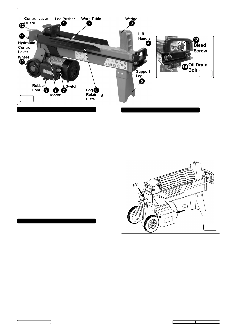
Fig.2 fig.1 fig.3 – Sealey LS370H User Manual
Page 2
p
Warning! ensure you read, understand and apply the safety
instructions before use.
5.1
the control system of the log splitter requires the operator to use both
hands. the left hand will control the hydraulic control lever (A) and the
right hand controls the motor push button (B) as shown below in fig.3.
If either hand is removed from the controls the log pusher stops.
When both hands are removed from the controls the ram retracts and
the log pusher automatically returns to the start position.
p
Warning! this system has been designed to prevent the
operator from handling the log during the splitting process. for
safety reasons the operator must not ask a second person to
place or handle the log. the system is designed to be operated
by one person only.
5. operating instrUctions
3. proDUct featUres
4. set Up & preparation
refer to figs.1 and 2 above. the log splitter has an electrically powered
`
hydraulic ram situated inside the main beam. When the ram is
operating it will protrude from the end of the beam by up to 52cm.
3.1
log pusher. the log pusher travels along the main beam and brings
logs to bear against the splitting wedge. the log pusher is recessed
and can be used as a lifting handle when two people are moving the
unit.
3.2
Work table. logs are placed onto the work table and slid along until
they are in contact with the splitting wedge.
3.3
splitting Wedge. After prolonged use it may be necessary to sharpen
the wedge with a fine toothed file.
3.4
lifting handle. this handle is mainly used when moving the log splitter
on its wheels.
3.5
support leg. Works in conjunction with the two rubber feet (9) at the
other end of the unit.
3.6
log retaining plates. Aligns log prior to splitting.
3.7
switch. this motor switch must be used in conjunction with the
Hydraulic control lever (11).
3.8
motor. Powers the hydraulic ram.
3.9
rubber feet. Holds wheels off ground when unit is horizontal.
3.10
Wheels. use in conjunction with lifting handle (4).
3.11
hydraulic control lever. this Hydraulic control lever must be used
in conjunction with the motor switch (7).
3.12
control lever guard. this guard protects the Hydraulic control lever
against damage and inadvertent operation.
3.13
Bleed screw. must be open during operation and closed when
transporting the unit.
3.14
oil Drain Bolt. Gives access to top up or change the oil and has a built
in dipstick.
4.1 assembly. Bolt the support leg (5) to the log splitter using the 5 nuts
and bolts provided.
4.2
moving the log splitter. the log splitter rests on the support leg and
two rubber feet just in front of the wheels which are slightly off the
ground. to move the log splitter take hold of the handle (4) and lift the
front end up by about 30° so that the unit tips off the feet and onto the
wheels. move the unit to the required position. As you lower it to the
ground it will rest back onto the rubber feet.
4.3
operating position. We do not recommend that the log splitter is used
on the ground as the operators face will tend to be too near to the area
of operation and therefore vulnerable to flying wood chips and debris.
With the help of another person lift the log splitter onto a stable, flat and
level work surface 60 to 75cm high.
4.4
ram extension. remember that when the unit operates the ram will
extend out of the front of the main beam by up to 52cm. therefore
allow plenty of clearance beyond the front of the unit.
4.5
Bleed screw. see fig.2 -13. Before operating the log splitter the bleed
screw should be opened by 3 turns to allow air to pass in and out of
the oil tank. Air flow through the bleed screw should be detectable
during operation. When moving the log splitter close the bleed screw to
avoid spilling oil.
remember to open it again before the next operation.
p
Warning! Failure to open the bleed screw (see 4.5 above) will
trap air within the system. The continued compression and
decompression of this air will blow out the seals of the hydraulic
system and cause permanent damage to the log splitter thus
invalidating your warranty.
fig.2
fig.1
fig.3
5.2
A number of factors will affect the way a log splits including the hardness
of the wood and the complexity of the grain. A log which includes the
junction of another branch or branches may be more difficult to split.
Ideally the ends of the log should be cut square otherwise the log may
change position when pressure is applied to it.
5.3
Always split a log along its grain.
never attempt to split a log laid
across the machine as this could be dangerous for the operator and
could seriously damage the machine.
5.4
Place a log onto the table as shown above in fig.3 ensuring that it sits
between the log guides and the grain is aligned with the splitting wedge.
5.5
operate the controls. If the log becomes misaligned between the log
pusher and the splitting wedge when the log pusher first makes
contact with the log, let go of the controls and allow the ram to retract.
rotate/reposition the log and try again. If the log will not sit properly on
the table or continues to be misaligned under pressure it should be
discarded or have the ends recut square.
p
Warning! if the log does not split within 5 seconds the controls
must be released. after more than 5 seconds use the oil will
become overheated and the machine could be damaged. failure to
split the log means that its hardness is beyond the capacity of the
machine
and the log should be discarded to protect the log splitter.
5.6
do not allow logs to ride up the splitting wedge as shown in fig.4.
When pressure is applied to the upper part of the wedge only this
could break the wedge or damage the machine.
Original Language Version
ls370H & ls520H Issue: 3(I) - 30/10/13
© Jack sealey limited