Fig. 2, Fig. 1, Fig. 3 fig. 4 fig. 5 – Sealey TP6901 User Manual
Page 2: Introduction & specification, Assembly (all models)
2. INTRODUCTION & SPECIFICATION
9ltr capacity devices constructed from composite materials. uses
manual pump or compressed air supply to generate vacuum,
depending on model. suitable for the extraction of all types of engine,
transmission and lubricating oils from cars, motorcycles, marine
engines, stationary engines and industrial machinery. suitable also
for low viscosity fluids such as water. supplied with Ø6 and Ø10mm
suction probes and brake/clutch bleeding hose. uses probes to
extract engine oil through the dipstick tube.
Model No: . . . . . . . . . . . . . . . . .TP6901.V2 . . . . . . . .TP6903.V2 & TP6904.V2
capacity:. . . . . . . . . . . . . . . . . . . . . . . . . 9ltr . . . . . . . . . . . . . . . . . . . . . . . . . 9ltr
Probes: . . . . Ø6 x 1100mm, Ø10 x 1100mm . . . Ø6 x 1100mm, Ø10 x 1100mm
hose: . . . . . . . . . . . . . . . . . . Ø8 x 1100mm . . . . . . . . . . . . . . . . .Ø8 x 1100mm
Air Pressure . . . . . . . . . . . . . . . . . . . . . .n/A . . . . . . . . . . . . . . . . . . . . . . . .90psi
Air consumption: . . . . . . . . . . . . . . . . . .n/A . . . . . . . . . . . . . . . . . . . . . . . 5cfm
max oil temp: . . . . . . . . . . . . . . . . . . 70°c . . . . . . . . . . . . . . . . . . . . . . . . 70°c
3.
ASSEMbLY (ALL MODELS)
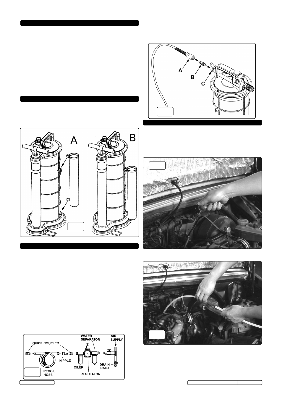
fig. 2
3.1
cut the nylon ties which are holding the tube storage unit to
the main tank. Identify the mounting hooks on the tank (see
fig.1A). Place the mounting loops on the storage tube over
the hooks on the tank and push downwards to snap the
storage tube into place as shown in fig.2b.
when using a workshop air supply, the recommended hook-up is
shown below.
4.1. ensure that the air valve (see fig.7) is in the "off" position
before connecting to the air supply.
4.2. You will require an air pressure and an air flow (cfm) according
to the specification above in section 2.
WARNING! ensure the air supply is clean and does not
exceed the pressure quoted. too high an air pressure and/or
unclean air will shorten the life of the extractor due to
excessive wear and may be dangerous, causing damage
and/or personal injury.
4.3. drain the compressor air tank daily.
4.4. clean compressor air inlet filter weekly.
4.5. line pressure should be increased to compensate for unusually
long air hoses (over 8 metres). the minimum bore for hose
and fittings is 1/4”.
4.6. Keep hoses away from heat, oil and sharp edges. check hoses
for wear and make certain that all connections are secure.
4.
AIR SUPPLY (TP6903.V2 & TP6904.V2)
fig. 1
5. AIR OPERATION (TP6903.V2 & TP6904.V2)
Ensure you read, understand and apply the Section 1 Safety
Instructions.
5.1.
first ensure that the vehicle is level. run the engine for
approximately five minutes to ensure that the oil is warm.
switch off engine.
WARNING! ensure oil temperature does not exceed 70°c.
5.2.
remove the oil dipstick from the engine.
5.3.
Insert the appropriate extracting probe into the dipstick tube
making sure it reaches the bottom of the sump. depending
on the vehicle it may be necessary to insert the wire supplied
in order to keep the tube more rigid as it passes down into
the sump. connect the extracting probe to the main suction
tube using the black rubber adaptor. the tubes are a push fit
into the adaptor.
4.7.
Pull back the sleeve on the quick coupling (see fig.3A) and
remove the male threaded air coupling (see fig.3b). wrap the
thread in Ptfe tape and screw the coupling into the air valve
mounted at the rear of the handle (see fig.3c). do not over
tighten.
fig. 3
fig. 4
fig. 5
Original Language Version
tP6901.V2, tP6903.V2, tP6904.V2 Issue: 1-28/01/13
© Jack sealey ltd