Sealey AK462DX User Manual
Ak462dx.v2, Instructions for, Model no
3.1. Ensure the air valve is in the "Off" position before connecting to the air supply.
3.2. You will require an air pressure of 8 - 9 bar.
3.3. p WARNING! Ensure the air supply is clean and does not exceed pressures
specified in these Instructions. Too high an air pressure and/or unclean air will
shorten the drainer life due to excessive wear, and may be dangerous, causing
damage and/or personal injury.
3.4. Drain the air tank daily. Water in the air line may damage the drainer.
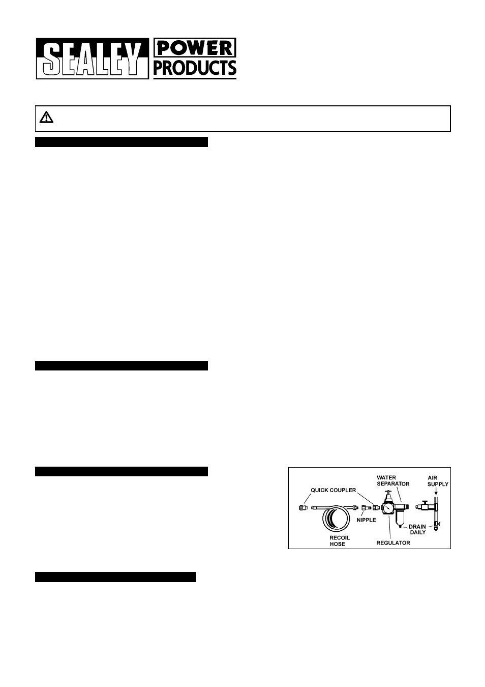
3.5. Clean the air inlet filter screen weekly. The recommended hook-up is shown in fig.1.
3.6. Line pressure should be increased to compensate for unusually long air hoses
INSTRUCTIONS FOR:
GRAVITY & SUCTION FEED AIR DISCHARGE
CANTILEVER OIL DRAINER
Model No:
AK462DX.V2
Thank you for purchasing a Sealey product. Manufactured to a high standard this product will, if used according to these instructions
and properly maintained, give you years of trouble free performance.
AK462DX.V2 - 1 - 071102
1. SAFETY INSTRUCTIONS
IMPORTANT: PLEASE READ THESE INSTRUCTIONS CAREFULLY. NOTE THE SAFE OPERATIONAL REQUIREMENTS, WARNINGS & CAUTIONS.
USE THE PRODUCT CORRECTLY AND WITH CARE FOR THE PURPOSE FOR WHICH IT IS INTENDED. FAILURE TO DO SO MAY CAUSE
DAMAGE AND/OR PERSONAL INJURY AND WILL INVALIDATE THE WARRANTY. PLEASE KEEP INSTRUCTIONS SAFE FOR FUTURE USE.
2. INTRODUCTION & ASSEMBLY
1.1.
GENERAL SAFETY
p
WARNING! Ensure Health & Safety, local authority, and general workshop practice regulations are adhered to when using this equipment.
3
Familiarise yourself with the application and limitations of the oil drainer, as well as the potential hazards.
p
WARNING! Disconnect the drainer from the air supply before changing accessories, servicing or performing any maintenance.
3
Maintain the drainer in good condition (use an authorised service agent).
3
Replace or repair damaged parts. Use genuine parts only. Unauthorised parts may be dangerous and will invalidate the warranty.
3
Keep the work area clean, uncluttered and ensure there is adequate lighting.
3
Keep the drainer clean for best and safest performance.
3
Maintain correct balance and footing. Ensure the floor is not slippery and wear non-slip shoes.
3
Keep children and unauthorised persons away from the working area.
p
WARNING! ensure correct air pressure is maintained and not exceeded.
3
Keep air hose away from heat, oil and sharp edges. Check air hose for wear before each use, and ensure that all connections are secure.
7
DO NOT use the drainer for any purpose other than that for which it is designed.
7
DO NOT operate the drainer if any parts are damaged or missing as this may cause failure and/or personal injury.
7
DO NOT stand on the drainer.
7
DO NOT adjust or tamper with the safety valve.
7
DO NOT move the drainer by the hose, or yank the hose from the air supply.
7
DO NOT place attachments close to your face (especially eyes, ears, etc.) and do not point hose at other persons or animals.
7
DO NOT allow untrained persons to operate the drainer.
7
DO NOT operate the drainer when you are tired, under the influence of alcohol, drugs or intoxicating medication.
7
DO NOT leave the drainer operating unattended.
7
DO NOT direct air from the air hose at yourself or others.
3
When not in use disconnect from the air supply, vent reservoir and store in a safe, dry, childproof area.
3
Dispose of waste oil in accordance with local authority regulations.
p
WARNING! DO NOT pollute the environment by allowing uncontrolled discharge of waste oil.
2.1. Introduction
2.1.1. The AK462DX.V2 has a steel fabricated 100ltr reservoir with suction probes and air discharge. The unit features a cantilever oil drain
pan which is suitable for use either under a lift or on the forecourt. Drain pan utilises vacuum suction when in the down position and is
fitted with bogey wheels for easy manoeuvring. Fitted with oil level indicator tube and supplied with Mercedes adaptor plus a selection of probes.
2.2. Assembly
Note: Numbers in brackets refer to item numbers on the Parts Diagram
2.2.1. Remove the bolt, washer and nut (48, 49 & 50) from the support bar (82).
2.2.2. Move the support bar (82) to the vertical position and engage the locking pivot bar (78) into the guide on the side of the reservoir.
2.2.3. Align the holes in the support bar (82) and the bracket on the oil pan (42), fit the bolt (48) and secure using the washer and nut (49 & 50).
2.2.4. Loosen the handle retaining bolts at the back of the reservoir, insert the handle and tighten the bolts.
2.2.5. The oil drainer is now ready for use.
3. AIR SUPPLY
Fig.1.
(over 8 metres). The minimum hose diameter should be 10mm I.D. and fittings must have the same inside dimensions.
3.7. Keep hose away from heat, oil and sharp edges. Check hoses for wear, and make certain that all connections are secure.
p
WARNING! Ensure that you read, understand and apply the safety instructions in Section 1.
p
WARNING! Ensure all valves are CLOSED before applying air pressure to the unit.
Note: Prior to initial use, open all valves, allow any residual pressures to vent and then close all the valves.
Note: Numbers in brackets refer to item numbers on the Parts Diagram.
4.1. Gravity feed oil drainer
4.1.1. With the oil drainer pan in the raised position, open the oil input valve (95) and the ball tap valve (34).
4.1.2. Remove the vehicles oil drain plug and the oil will drain via the oil pan into the reservoir under gravity.
4. OPERATION