Sealey AK449D User Manual
Ak449d, Waste oil drain collector, Model no
Item Part No
Description
1 AK449D.01
BACK WHEEL CASTER
1 AK449D.02
FRONT WHEEL
3 AK449D.03
AXLE
4 AK449D.04
BASE PLATE
5 AK449D.05
CLAMPING SET
6 AK449D.06
HANDLE
Item Part No
Description
7 AK449D.07
SQUARE TUBE CLAMP SET
8 AK449D.08
BALL VALVE
9 AK449D.09
OIL PAN
10 AK449D.10
OIL PIPE
11 AK449D.11
HEIGHT RING
12 AK449D.12
BOLT
IMPORTANT: No liability is accepted for incorrect use of this equipment.
WARRANTY: Guarantee is 12 months from purchase date, proof of which will be required for any claim.
INFORMATION: For a copy of our catalogue and latest promotions call us on 01284 757525 and leave your full name, address and postcode.
NOTE: It is our policy to continually improve products and as such we reserve the right to alter data, specifications and component parts without prior notice.
INSTRUCTIONS FOR:
WASTE OIL DRAIN COLLECTOR
Model No:
AK449D
Thank you for purchasing a Sealey product. Manufactured to a high standard this product will, if used according to these instructions
and properly maintained, give you years of trouble free performance.
1. SAFETY INSTRUCTIONS
IMPORTANT: PLEASE READ THESE INSTRUCTIONS CAREFULLY. NOTE THE SAFE OPERATIONAL REQUIREMENTS, WARNINGS AND CAUTIONS.
USE THIS PRODUCT CORRECTLY AND WITH CARE FOR THE PURPOSE FOR WHICH IT IS INTENDED. FAILURE TO DO SO MAY CAUSE DAMAGE
AND/OR PERSONAL INJURY AND WILL INVALIDATE THE WARRANTY. RETAIN THESE INSTRUCTIONS FOR FUTURE USE.
3. ASSEMBLY
3 Use drainer in a suitable work area. Keep area clean and tidy, free from unrelated materials and
ensure there is adequate lighting.
3 Ensure the floor is not slippery and wear non-slip shoes.
3 Wear appropriate protective clothing.
3 Keep the drainer clean and in good condition for best and safest performance.
3 Keep children and unauthorised persons away from the work area.
3 Dispose of waste liquids in accordance with local authority regulations.
7 DO NOT position drainer in such a way that it will cause potential hazards when moving, holding for
draining or storing.
p WARNING! DO NOT allow uncontrolled discharge of fluids thus polluting the environment.
4.1.
Collection of waste oil.
4.1.1
The AK449D is designed for use with 25ltr drums or similar containers that will fit onto the base plate.
If a container laps over the edge of the base do not use it.
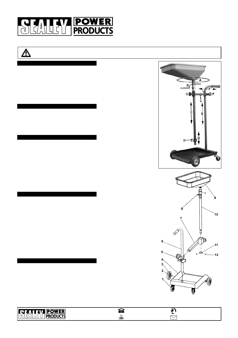
4.1.2
The AK449D has a number of adjustments that allow the drainer to adapt to different sizes of
containers and different workshop conditions. The overall height of the unit can be adjusted using a
combination of clamps (C) and (E) as shown in fig.1. The centreline of the oil pipe and pan can be
adjusted using clamp (F) and the oil pan will rotate through 360
O
.
4.1.3
If a task is repeated often using the same container and/or vehicle, the set up can be easily repeated
by using the locking rings (D) to mark the position of the oil pipe in relation to the clamp (C).
4.1.4
Loosen the oil pipe clamp (fig.1-C) and raise the pipe and pan to clear the chosen container. The
container must rest flat and level on the base. Adjust the height of the oil pipe and pan so that the
drainer will pass under the raised vehicle.
4.1.5
Adjust the height and positioning of the unit below the sump drain point. To allow the oil to pass
directly into the container open the ball valve as shown in fig.1-B. When the container becomes full
after a number of draining operations the ball valve can be shut whilst changing the container.
4.1.6
Do not move the unit with oil still in the pan. Always ensure that any oil is drained down to the lower
container before moving the unit.
4. OPERATING INSTRUCTIONS
AK449D - 1 - 021204
2.1. Introduction.
Mobile waste oil drainer for use with 25ltr or other suitable containers. Telescopic drain
pan with filter grid and ball valve control. Arm fully adjustable in height and depth and fitted with
locking nuts for predetermined height selection. Heavy-duty design trolley with handle, two swivel
castors and two fixed wheels.
2.2. Specification.
Min. Height to Pan : 1090mm
Max. Height to Pan : 1740mm
Capacity : Dependent on container
Gravity Feed : Yes
2. INTRODUCTION & SPECIFICATION
NOTE: Instructions refer to numbers on the parts diagram. You will need a 5mm Allen Key unless otherwise stated.
3.1
Attach the fixed front wheels (2) to the base plate (4) by inserting the stub axles into the bushes
provided. Retain with 5mm hex socket screws.
3.2
Insert the back wheel caster axles (1) into the bushes provided and retain with 5mm hex socket screws.
3.3
Slide the clamping set (5) onto the handle (6) and insert the handle into the socket at the rear of
the base plate. Retain the handle by tightening the 5mm hex socket grub screw to be found in the
side of the socket on the underside of the base plate.
3.4
Slide the square tube clamp set (7) into the clamping set (5) and tighten the retaining knob.
3.5
Slide the oil pipe (10) through the square tube clampset (7) and tighten the retaining knob.
3.6
Slide the height selection rings (12) over the bottom end of the oil pipe and lock them in
the required position by tightening the two hex socket grub screws using a 4.5mm Allen key.
3.7
Insert the outlet of the oil pan into the top of the ball valve assembly. Ensure that it is fully seated and
retain it by tightening the 5mm hex socket screw in the side of the collar. The oil pan is not gripped by the
fixing and can be rotated through 360
O
as indicated in fig.1.
Fig 1
5. REPLACEMENT PARTS
01284 757500
01284 703534
Sole UK Distributor
Sealey Group,
Bury St. Edmunds, Suffolk.
www.sealey.co.uk
Web