Sealey CST981 User Manual
Cst 981, Hand trolley, 4 - wheeled model no, Instructions for
INSTRUCTIONS FOR:
HAND TROLLEY, 4 - WHEELED
Model No:
CST 981
Thank you for purchasing a Sealey product. Manufactured to a high standard this product will, if used according to these instructions
and properly maintained, give you years of trouble free performance.
CST 981 - 0064 - 140499
1. SAFETY INSTRUCTIONS
IMPORTANT: PLEASE READ THESE INSTRUCTIONS CAREFULLY. NOTE THE SAFE OPERATIONAL REQUIREMENTS, WARNINGS & CAUTIONS.
USE THE PRODUCT CORRECTLY AND WITH CARE FOR THE PURPOSE FOR WHICH IT IS INTENDED. FAILURE TO DO SO MAY CAUSE
DAMAGE OR PERSONAL INJURY, AND WILL INVALIDATE THE WARRANTY. PLEASE KEEP INSTRUCTIONS SAFE FOR FUTURE USE.
4. ADJUSTMENTS
2. SPECIFICATION
Max. Load . . . . . . . . . . . . . . .150kg
Platform Height . . . . . . . . . . .160mm
Dimensions - (LxWxH)
Folded . . . . . . . . . . . .495x420x230mm
Overall . . . . . . . . . . .710x420x960mm
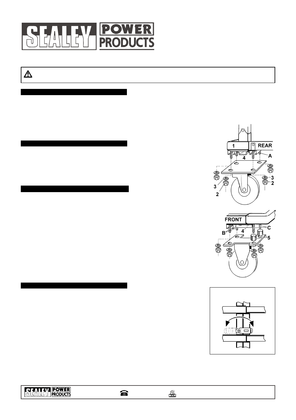
Before assembling wheels raise rear guard and handle assembly - see para. 4.1.1
3.1
Rear Wheels - Castor
3.1.1
Remove rear corner plastic trim (fig.1.1) (to give access to screw head).
3.1.2
Remove 4 nuts (2) and spring washers (3).
3.1.3
Place bridge piece (4) as shown in fig.1 and fit castor wheel mounting plate over screws.
3.1.4
Replace the 4 washers and nuts, tighten and replace trim.
3.1.5
Repeat for the second rear wheel.
Note! 1 screw is shorter than the other 3 and goes in position A fig.1.
3.2
Front Wheels - Fixed
3.2.1
Fit 2 short screws though mounting holes in positions B fig.2.
3.2.2
Place bridge piece (4) as shown in fig. 2 and fit wheel mounting plate over screws.
3.2.3
Fit 2 washers and nuts finger tight.
3.2.4
Fit 2 short screws though holes in positions C, though spacers (5) and through wheel mounting plate.
3.2.5
Fit washers and nuts and tighten all 4.
3.2.6
Repeat for the second front wheel.
4.1
Rear Guard and Handle
4.1.1
To lift the rear guard and handle assembly from the folded position, pull it upward until it locks.
4.1.2
The handle is raised by pulling upward until it latches.
4.1.3
To lower the handle, press down firmly, against spring load, the upper cross-bar of the guard
and, at the same time, push the handle down.
4.1.4
To fold the rear guard and handle assembly, press down the guard cross-bar and, at the same
time, push the handle forward.
4.1.5
To extend the load platform, lift catch (fig.3) and turn through 180
O
, then pull front and rear
platform sections apart. Ensure catch re-engages.
4.1.6
To close the extended platform, reposition catch, as 4.1.5, then push sections together.
Ensure catch re-engages.
Note! Only use trolley with platform fully closed or fully extended.
3. ASSEMBLY
3
Always load evenly with the centre of gravity of the load as near the centre of the trolley as possible.
3
Obtain additional support for large or wide loads to prevent tipping.
7
Do not overload the trolley - see Specification.
7
Do not leave unattended, especially when loaded, unless the wheels are chocked or the trolley otherwise secured.
7
Do not use trolley on uneven ground and do not run over curbs or steps - use a ramp.
7
Do not allow others to ride on the trolley.
7
Do not use the trolley if any part is significantly damaged, paying particular attention to the wheels.
Sole UK Distributor
Sealey Group,
Bury St. Edmunds, Suffolk.
01284 757500
E-mail:
01284 703534
NOTE: It is our policy to continually improve products and as such we reserve the right to alter data, specifications and component parts without prior notice.
IMPORTANT: No liability is accepted for incorrect use of product. WARRANTY: Guarantee is 12 months from purchase date, proof of which will be required
for any claim. INFORMATION: Call us for a copy of our latest catalogue on 01284 757525 and leave your full name and address including your postcode.
fig 2
fig 3
fig 1