Fig.4, Fig.5 – Sealey PT1170H User Manual
Page 2
4. OPERATING THE TRUCK
5. ADJUSTMENTS
6. MAINTENANCE
7. TROUBLE SHOOTING
WARNING! Always transport a load with the pallet raised from the ground by only 2 to 3cm.
WARNING! Pallets with an enclosed entry should not be used for lifting a load to a higher
level as the scissor action of the jack will force the woodwork apart. Only open bottomed
Euro type pallets can be used to raise a load to a higher level.
4.1
Before using the truck you must read and understand the safety instructions in Section 1. The truck
should only be operated by those persons who have been trained in its use.
4.2
The operator must be physically capable of pushing or pulling the load and must also be capable of
stopping a rolling load.
4.3
Before lifting any load the operator should check that the pallet is the correct width and length for the
truck and that the pallet itself is not damaged.
4.4
The operator should ensure that the load on the pallet is safe to move. If the load appears to be loosely
stacked, unevenly distributed, too high or too wide it should be repacked safely before moving. Also check that
the weight of the load is within the capacity of the truck.
4.5
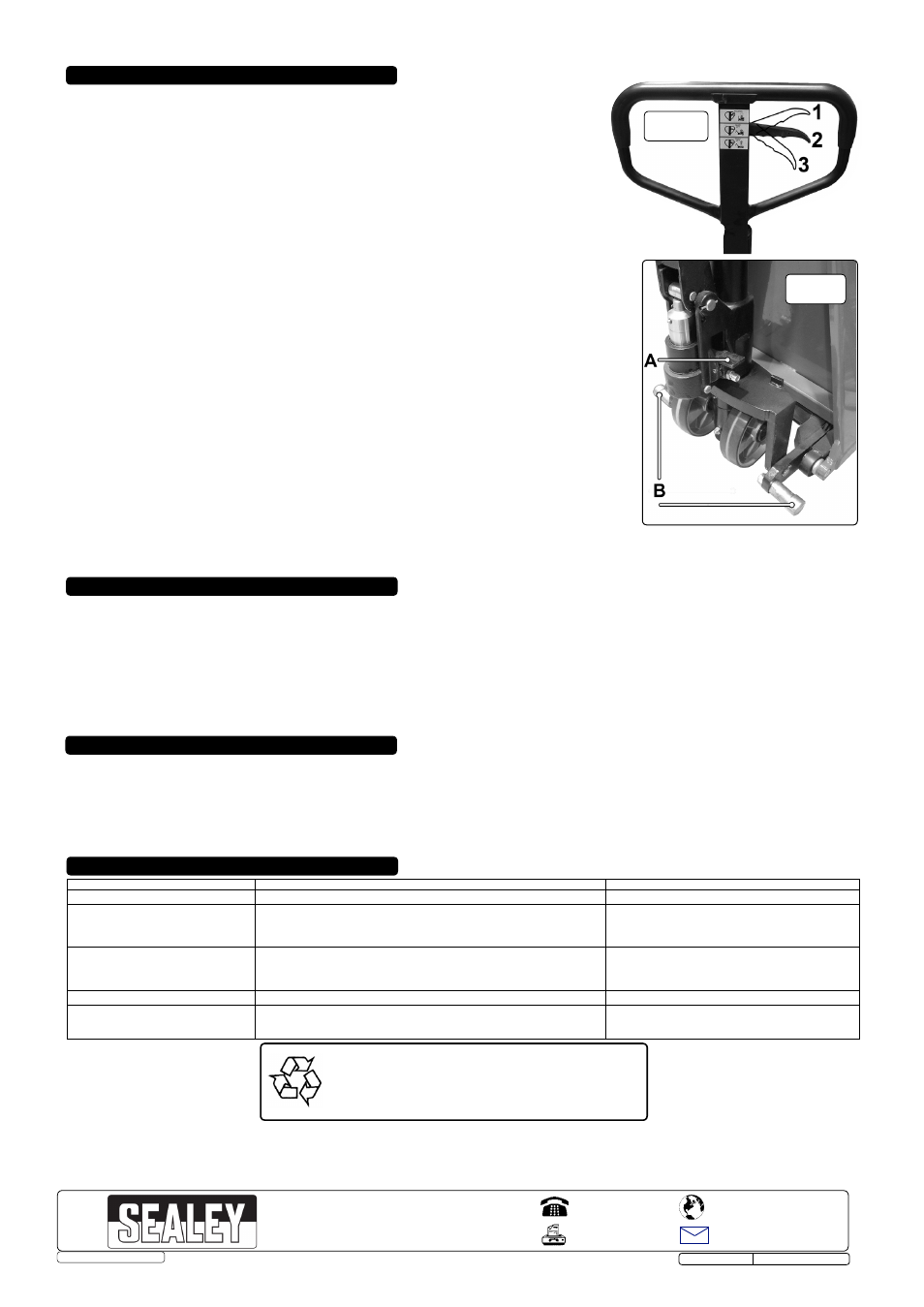
Lowering the truck. (See fig.4-1). Before inserting the truck into the pallet ensure that the truck forks are
in their lowest position by pulling the operating lever into the upper position and holding it there until the
truck has settled down to the lowest level.
4.6
Slow lift position. (See fig.4-2). The lever can now be released and will return to the middle position. Push
the truck into the pallet ensuring that it is fully inserted. If the pallet is shorter than the forks the load should
be placed at the centre point of the length of the forks. Pump the handle to raise the load slightly off the
ground in preparation for transporting the load to a new location. When the handle is pumped in this position
the load only rises slowly. Always transport a load with the truck in the lowest position.
4.7
Due care should be taken when manouvering a load to ensure that no collision takes place with any objects
or people.
4.8
The faster the truck is moved the more difficult it will be to stop it. Therefore proceed at a slow and even pace.
4.9
Bring the truck to a stop where required and lower the load to the floor by pulling the operating lever to its
highest position and holding it there until the load has settled to the floor. Alternatively the load can be
lowered by pressing the foot pedal. (See fig.5A).
4.10
It is not recommended that the load is lowered whilst the truck is still moving as a sudden stop may
dislodge the load causing damage to property and/or people.
4.11
Quick lift position. (See fig.4-3). To lift a pallet quickly to a higher level push the operating lever to
its lowest position where it will latch.
NOTE: Only open bottomed Euro type pallets can be raised to a
higher level. Pump the handle up and down to lift the load higher. When the forks reach their maximum
height the lifting action will stop even if you continue to pump the handle. As the load rises the stabilising
pins attached to the legs either side of the wheels (See fig.5B) will begin to make contact with the ground.
Above the height of 300mm the rear wheels are no longer in contact with the ground. This is a safety
feature designed to prevent the moving of the load when the forks are raised to a high level.
4.12
When the truck is not in use, lower the forks and park the truck where it will not be a hazard.
fig.4
5.1
The operating lever mechanism is adjusted in the factory but should the adjustment be lost or the mechanism not perform as it should it may be
necessary to re-adjust to restore correct operation.
5.2
Before making any adjustments first check that the oil level is correct. See Maintenance section below.
5.3
Test the performance of the truck in each lever position. If it does not function correctly in any position make adjustments to the nut at the end of the
release rod chain. (See Part No.104 on the pump assembly parts diagram).
5.4
If the quick lift function will not operate or the forks will not lift, turn the adjusting nut anticlockwise.
5.5
If the slow lift function will not operate or the forks will not lower, turn the nut clockwise.
5.6
If turning the nut at the end of the release rod chain does not cure the problem make further adjustments in conjunction with the adjusting bolt beneath
the release pedal. (See Part No.318 on the pump assembly parts diagram). Turn the bolt in the same direction as the adjusting screw. Make small
changes to each adjustment in turn until the truck begins to function properly.
NOTE: The screw situated towards the top of the piston is dual purpose. The screw is loosened when purging air from the system and also is removed when the
oil requires topping up. (See fig.3E).
6.1
If the forks will not rise to the highest level the oil level should be topped up. Otherwise the oil level should be checked every six months. Only use
hydraulic oil which conforms to ISO VG32. The viscosity should be 32cSt at 40°C .
6.2
To purge air from the system loosen the screw at the top of the piston (See fig.3E). Slowly push the handle downwards to release any air then retighten
the screw.
6.3
Apply a long life grease to all bearings and shafts once a month.
THE PROBLEM
THE CAUSE
THE SOLUTION
1 The forks do not reach maximum height. Hydraulic oil level too low.
Top up the oil.
2 The forks do not raise.
No or low hydraulic oil.
Fill/top up with hydraulic oil.
The oil is contaminated.
Change the oil.
The lifting/lowering mechanism needs adjustment.
Follow procedure in Section 5.
Air in the hydraulic system.
Purge the air as described in Section 5.
3 The forks will not descend.
The lifting/lowering mechanism needs adjustment.
Adjust as described in Section 5.
Truck stored in raised position allowing exposed piston rod to corrode and jam.
Lubricate rod regularly and store truck in lowered position.
The movement of the forks is obstructed.
Remove obstruction
4 Leaks
Seals worn,damaged or cracked.
Replace seals.
5 No difference in lifting speed between
The lifting/lowering mechanism needs adjustment.
Adjust as described in Section 5.
quick and slow handle positions.
Release valve not fully closed due to impurities in oil.
Change the oil.
fig.5
PT1170H.V2 Issue No:1- 12/02/14
NOTE: It is our policy to continually improve products and as such we reserve the right to alter data, specifications and component parts without prior notice.
IMPORTANT: No liability is accepted for incorrect use of this product.
WARRANTY: Guarantee is 12 months from purchase date, proof of which will be required for any claim.
INFORMATION: For a copy of our latest catalogue and promotions call us on 01284 757525 and leave your full name and address, including postcode.
01284 757500
01284 703534
Sole UK Distributor, Sealey Group,
Kempson Way, Suffolk Business Park
,
Bury St. Edmunds, Suffolk,
IP32 7AR
www.sealey.co.uk
W e b
© Jack Sealey Limited
Original Language Version
Environmental Protection.
Recycle unwanted materials instead of disposing of them as
waste. All tools, accessories and packaging should be sorted,
taken to a recycle centre and disposed of in a manner which
is compatible with the environment.