Fig.5, Assembly, Fig.4 fig.6 – Sealey API16 User Manual
Page 2: Maintenance
API16 Issue no.1 20/06/14
fig.5
NOTE: It is our policy to continually improve products and as such we reserve the right to alter data, specifications and component parts without prior notice.
IMPORTANT: no liability is accepted for incorrect use of this product.
WARRANTY: Guarantee is 12 months from purchase date, proof of which will be required for any claim.
INFORMATION: For a copy of our latest catalogue and promotions call us on 01284 757525 and leave your full name and address, including postcode.
01284 757500
01284 703534
Sole UK Distributor, Sealey Group,
Kempson Way, suffolk Business Park
,
Bury st. edmunds, suffolk,
IP32 7Ar
www.sealey.co.uk
Original Language Version
© Jack sealey Limited
Parts support is available for this product. To obtain a parts listing and/or diagram,
please log on to www.sealey.co.uk, email [email protected] or telephone 01284 757500.
287mm
centres setting
(for enclosure fitting)
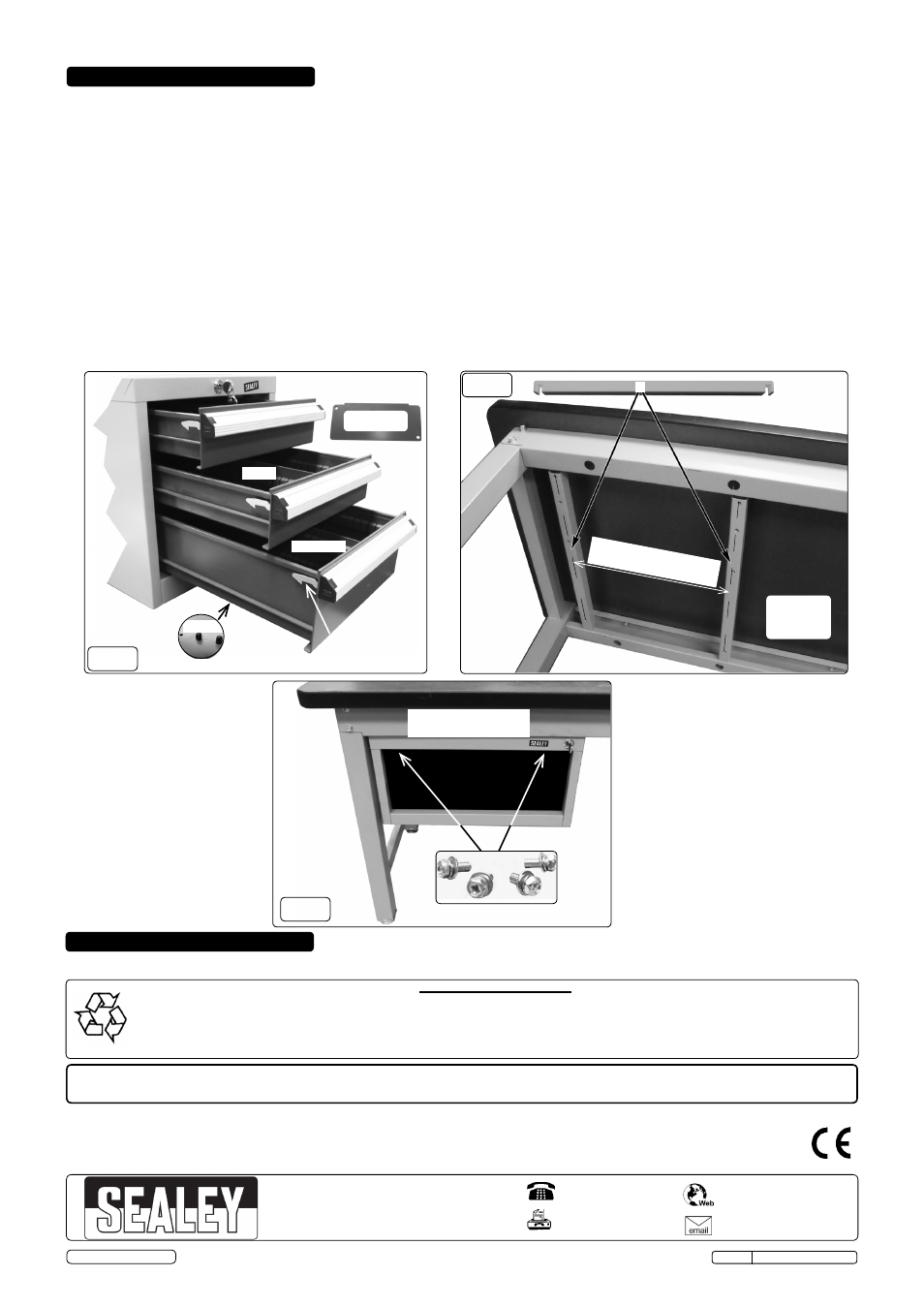
5. ASSEMBLY
5.1.
Drawer removal from enclosure
5.1.1. Unlock the drawer if required and open the drawer fully and squarely until it stops (fig.2 & 4). The ratchet catch, which safely holds the
drawers shut, releases when the drawer handle is gripped. remove the loose components, items 3,4,5 and 6.
5.1.2. With the drawer fully open against the stop, place one hand beneath the drawer and the other on the handle.
5.1.3. Lift the drawer and withdraw. See fig.2 for drawer roller path and fig.3 for the drawer roller.
5.2.
Fitting the enclosure to the bench
5.2.1. Locate the two bridge channels from beneath the bench at the required centres (fig.1) and (fig.5). As a suggestion only; position the
bridge channels centrally about the bench width for best access.
5.2.2. offer the empty dawer enclosure up to the bridge channels aligning slots to the captive nut holes in the bridge channels.
5.2.3. A second person is required to screw the enclosure to the bridge channels.
DO NOT tighten at this stage.
5.2.4 With all four screws fitted (item 8), with at least three threads engaged on each nut; slide the enclosure to the required position (fig.6)
and tighten all screws.
5.3.
Drawer Mullion Partition
5.3.1. Fit (item 3 and 3A) centrally with self tapping screws (item 5) through the pre-punched holes. transom plates (item 4) partitioning as
required.
5.3.2. Fit the rubber safety caps (item 6) to all self tapping screw projections, from the underside of the drawer (fig.4).
5.3.3. Locate the drawer rollers (fig.3) with the enclosure runners (fig.2) and slide the drawer/drawers fully back into the enclosure. Generally
the reverse of removal.
DO NOT force at any stage.
fig.4
fig.6
example position only
(drawers removed)
5 & 6
6. MAINTENANCE
Underside
6.1.
Lubricate the drawer runner bearings and track with a general purpose grease every 6 months. Wipe off excess with a dry cloth.
Environmental Protection
Recycle unwanted materials instead of disposing of them as waste. All tools, accessories and packaging should be
sorted, taken to a recycling centre and disposed of in a manner which is compatible with the environment.
When the product becomes completely unserviceable and requires disposal, dispose of the product according to local
regulations.
3 & 4
3A & 4A
ratchet catch
7
155 x 65 (4)
155 x 110 (4A)
transom plates
(8)
View from
beneath
bench