Ap6572e, Fig.a fig.b fig.c, Extension pack – Sealey AP6572 User Manual
Page 3
AP6572 & AP6572E IssuE 5(A) 19/07/13
EXTEnSiOn pack
MoDEL no:
ap6572E
1.0 We recommend that this extension unit be
assembled by two people. the only tool
required is a rubber mallet.
DO nOT use a
hard faced hammer as this will damage the
surface finish of the cross beams. Make sure
that all the clips lock in place securely before
using the unit.
DO nOT use any parts that are
damaged and/or distorted as these may
assemble incorrectly and result in an
installation that is unsafe and which may cause
injury or damage when the shelves are loaded.
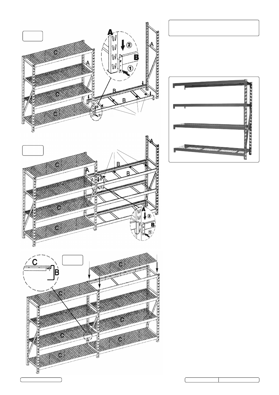
2.0 See fig.a. support one end frame 'A' in a
vertical position and attach the end of one
cross beam 'B' to it at the base of one of
the uprights. Ensure that both tags on the end
brackets engage properly with the slots in the
uprights as shown in the inset diagram. tap the
cross beam gently next to the end bracket so
that the beam is properly seated into the slots
in the upright. connect the other end of the
beam to the existing racking unit at the same
height and tap into place.
3.0 Attach another cross beam 'B' to the other side
of the end frames 'A' ensuring that it is at the
same level as the first cross beam. Attach 4
smaller cross beams 'D' between the main
cross beams 'B'.
4.0 See fig.B. continue to assemble the next
three pairs of cross beams at the heights
required. the end frames allow adjustment in
3" increments. Each pair of beams must be
mounted at the same height. Ensure that all
tabs on the cross beam brackets are fully
engaged in the slots in the uprights and that
the cross beams are properly tapped down into
place.
5.0 See fig.c. Each wire deck 'c' is reinforced
with four cross members welded onto the
underside of the mesh. Each of these cross
members has a turned down tab at either end
that must pass through slots in the cross
beams. Place a wire deck onto each pair of
cross beams as shown ensuring that it sits into
the recessed section on the top surface of
each cross beam and all tabs pass through the
slots in the cross beams as shown in the inset
diagram at the top of fig.c.
fig.A
fig.B
fig.c
carefully unpack the product and check the
contents against the list below. should any
items be missing or damaged make immediate
contact with your sealey dealer.
part Description ..................................Qty.
a
upright frame ............................................1
B
cross Beam (Long) ....................................8
c
Wire Mesh shelves ....................................4
D
cross Beam (short) .................................16
D
D
Original Language Version
© Jack sealey Limited
c
c
c
c