Fig.3, Fig.2 – Sealey STR003 User Manual
Page 2
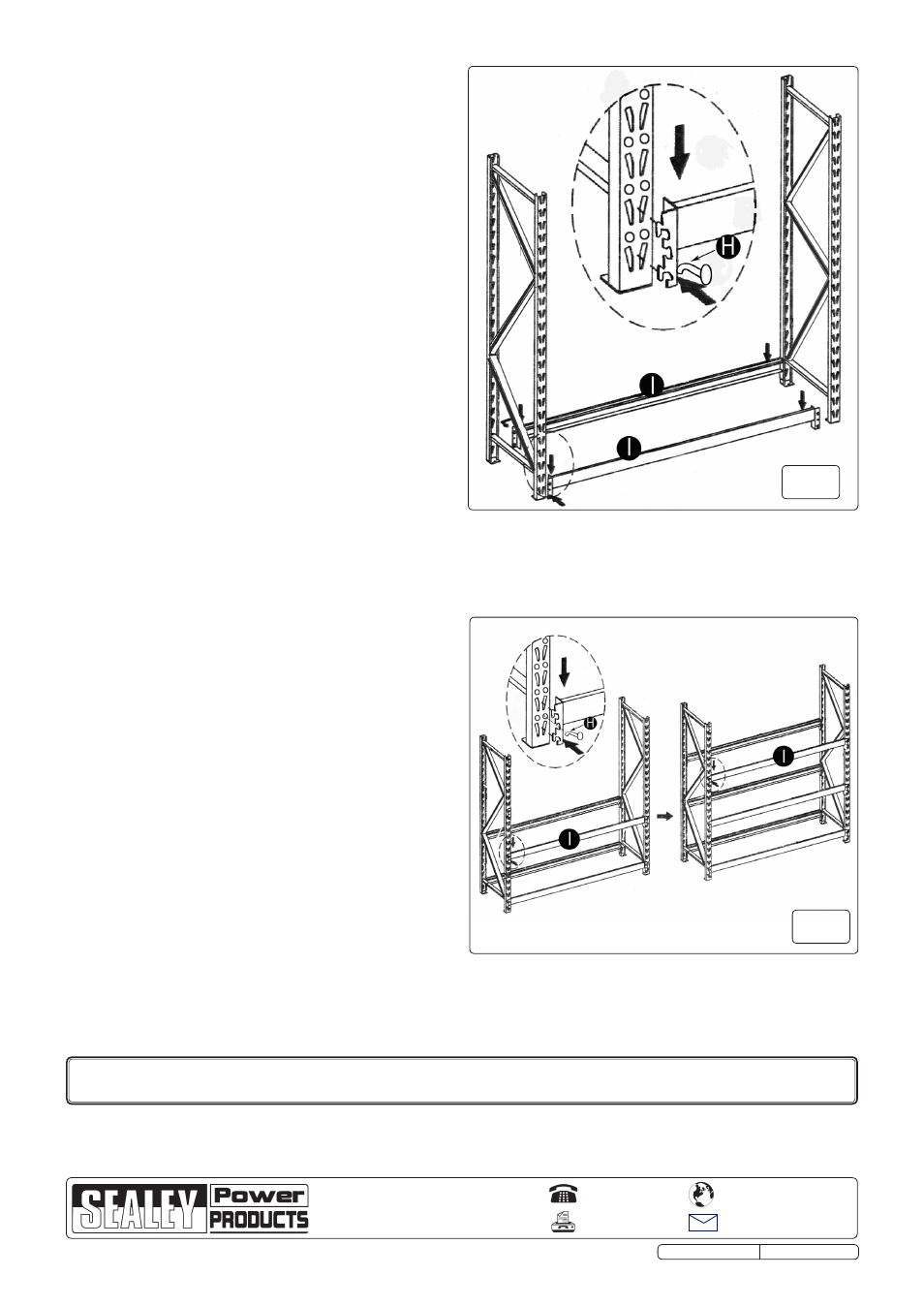
fig.3
4.2 Assembling the end frames. Refer to Fig.1.
4.2.1 Insert a rubber foot (E) into one end of each of the uprights (A1 & A2).
Note: Ensure that the end of the upright with the rubber
foot inserted is used as the base.
4.2.2 Place the uprights (A1 & A2) on the floor with the inner edges
facing each other and the rubber feet at the base.
4.2.3 take one horizontal brace (B1) and one spacer (D). Insert into
the upright (A2) at the base area drilled hole and loosely
secure using a M8 x 50mm bolt (f) and a M8 nut (G).
4.2.4 Place the other upright (A1) so that the horizontal brace (B1)
aligns with the base area drilled hole. take one of the diagonal
braces (c1) and insert into the upright (A1) so that the hole
aligns with the hole in the horizontal brace (B1) and the drilled
hole in the upright (A1). Loosely secure using a M8 x 50mm
bolt (f) and a M8 nut (G).
4.2.5 Align the other end of the diagonal brace (c1) with the
corresponding hole in the opposite upright (A2). take another
diagonal brace (c2) and align with the same hole on diagonal
brace (c1) and on the upright (A2). Loosely secure using a M8
x 50mm bolt (f) and a M8 nut (G).
4.2.6 Align the other end of the second diagonal brace (c2) with the
corresponding hole in the opposite upright (A1). take a third
diagonal brace (c3) and align with the second diagonal brace
(c2). Loosely secure both to the upright (A1) using a M8 x
50mm bolt (f) and a M8 nut (G).
4.2.7 Align the remaining end of diagonal brace (c3) with the top
hole of the opposite upright (A2). Place a horizontal brace (B2)
aligned with the diagonal brace (c3) and across to the
opposite upright (A1). Loosely secure the end of horizontal
brace (B2), along with the diagonal brace (c3) to the upright
(A2) using a M8 x 50mm bolt (f) and a M8 nut (G). Align the
other end of the horizontal brace (B2) with the top hole of the
upright (A1). Place a spacer in the gap and loosely secure with
a M8 x 50mm bolt (f) and a M8 nut (G).
4.2.8 check that the assembled frame is square and tighten all the
fasteners. repeat the procedure for the second frame
assembly.
4.3 Fitting the cross beams. Refer to Fig.2.
4.3.1 support one end frame in a vertical position and attach the end
of one cross beam (I) to it at the base of one of the uprights
(A). Ensure that both tags on the end bracket engage properly
with the slots in the upright as shown in the inset diagram. tap
the cross beam gently next to the end bracket so that the
beam is properly seated into the slots in the upright. Insert the
locking pin (H) so that it is against the beam. connect the other
end of the beam to the second end frame at the same
height,tap into place and secure with a locking pin (H).
4.3.2 Attach another cross beam (I) to the other side of the end
frames ensuring that it is at the same level as the first cross
beam.
4.3.3
See Fig.3. continue to assemble the next two pairs of cross
beams (I) at the heights required. the end frames allow
adjustment in 2" increments. Each pair of beams must be
mounted at the same height. Ensure that all tabs on the cross
beam brackets are fully engaged in the slots in the uprights
and that the cross beams are properly tapped down into place
then secured with a locking pin (H).
4.3.4 Extra components are available to create extra storage racks
as required (see section 3).
01284 757500
01284 703534
Sole UK Distributor, Sealey Group,
Kempson Way, suffolk Business Park
,
Bury st. Edmunds, suffolk,
IP32 7Ar
www.sealey.co.uk
Web
Original Language Version
NOTE: It is our policy to continually improve products and as such we reserve the right to alter data, specifications and component parts without prior notice.
IMPORTANT: no liability is accepted for incorrect use of this product.
WARRANTY: Guarantee is 12 months from purchase date, proof of which will be required for any claim.
INFORMATION: for a copy of our latest catalogue and promotions call us on 01284 757525 and leave your full name and address, including postcode.
fig.2
str003 & str003E IssuE 2 28/06/12
Parts support is available for this product.
To obtain a parts list and diagram please log on to www.sealey.co.uk, email [email protected] or phone 01284 757500