Fig.1 fig.2, Fig.4 fig.5 fig.6, Fig.3 – Sealey PTB141007 User Manual
Page 2: Environmental protection
Parts support is available for this product. To obtain a listing and/or diagram, please log on to: www.sealey.co.uk,
email: [email protected] or phone: 01284 757500
NOTE: It is our policy to continually improve products and as such we reserve the right to alter data, specifications and component parts without prior notice.
IMPORTANT: No liability is accepted for incorrect use of this product.
WARRANTY: Guarantee is 12 months from purchase date, proof of which will be required for any claim.
INFORMATION: For a copy of our latest catalogue and promotions call us on 01284 757525 and leave your full name and address, including postcode.
01284 757500
01284 703534
Sole UK Distributor, Sealey Group,
Kempson Way, Suffolk Business Park
,
Bury St. Edmunds, Suffolk,
IP32 7AR
www.sealey.co.uk
Original Language Version
PTB141007,PTB181510,PTB142511,PTB183015 Issue: 1 - 22/10/14
© Jack Sealey Limited
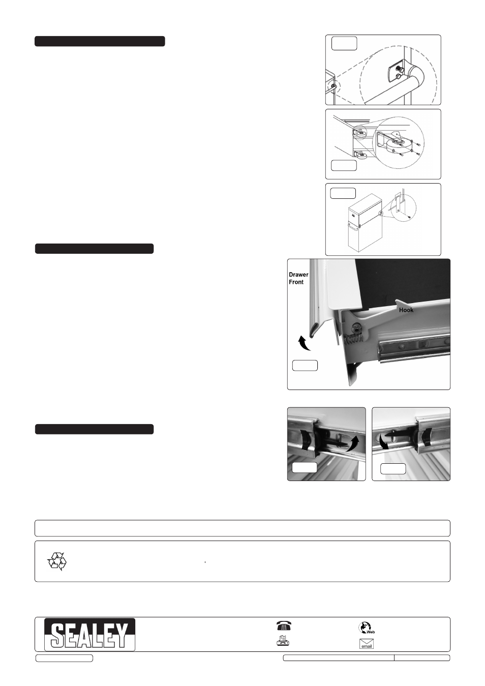
4. ASSEMBLY
WARNING! These cabinets are heavy! Two persons are required to complete the
assembly safely.
4.1.
Roll
Cab
Handle
Installation.
Position the handle over the holes in the roll cab, attach using the M6 x 12mm
hex bolts and tighten securely (fig.1). Assembling the handle first will make it easier
to handle the roll cab.
4.2.
Castor Installation.
4.2.1.
Lay the roll cab on its back carefully, protecting it with a soft mat placed on the floor.
4.2.2. Position the two rigid wheels in the centre of the rollcab.
4.2.3. Insert the M8 x 20mm hex bolts through the washers, then through the brackets and
into the base of the roll cab, tightening securely.
4.2.4. Repeat with the two swivel castors at each outer end.
4.2.5. Stand the rollcab upright carefully.
4.3.
Roll Cab and Top Chest Connection.
4.3.1. Remove the worktop from the rollcab.
4.3.2.
Place the top chest onto the rollcab.
4.3.3. Snap the connectors into the square holes on the back of the top chest (fig.3.).
4.3.4. Fasten the connectors with the screws provided.
fig.1
fig.2
5. OPERATION
6. MAINTENANCE
5.1.
Lift Latch Drawers.
5.1.1. To open: lift the drawer front whilst pulling it out (fig.4).
5.1.2. To close: shut the drawer firmly until the latch engages.
5.1.3. If the drawer does not latch, the hook (fig.4) may be misaligned or binding.
Bend the hook gently until it is parallel to the drawer edge and engages when
closed.
5.2.
To Remove Drawers
5.2.1. Pull drawer out almost fully.
5.2.2. Locate the black locking levers (figs. 5 & 6).
5.2.3. Facing the drawer; lift one lever up (fig.5), and push the other lever down
(fig.6).
5.2.4. With both levers held in this position, the drawer can be pulled out from the
slides.
5.3.
To Replace Drawers
5.3.1.
Extend the drawer runners from the cabinet.
5.3.2. Engage the slides on either side of the drawer carefully into the runners.
5.3.3. Push the drawer closed squarely until the drawer is closed fully, engaging the
locking levers as it goes.
fig.4
fig.5
fig.6
6.1.
Lubricate the drawer slides sparingly every six months.
6.2.
Clean the metalwork periodically with warm water and a mild detergent.
6.3.
Car wax may be used to restore the shine to the paintwork.
6.4.
Stubborn grease and oil marks can be removed by using a non-abrasive
cleaner.
fig.3
Environmental Protection
Recycle unwanted materials instead of disposing of them as waste. All tools, accessories and packaging should be sorted, taken to a recycling
centre and disposed of in a manner which is compatible with the environment. When the product becomes completely unserviceable and requires
disposal, drain off any fluids (if applicable) into approved containers and dispose of the product and the fluids according to local regulations.