Fig.1, Introduction & specifications – Sealey TIG160S User Manual
Page 3
2. INTRODUCTION & SPECIFICATIONS
2.2. Model No: . . . . . . . . . . . . . . . . . . . . . . . . . . . . TIG160S . . . . . . . . . . . . . . . . . . . . . .TIG180S . . . . . . . . . . . . . . . . . . . . . . . . TIG200S
Power Output:. . . . . . . . . . . . . . . . . . . . . . . . . . . 5-160A . . . . . . . . . . . . . . . . . . . . . . . 5-180A. . . . . . . . . . . . . . . . . . . . . . . . . 5-200A
Duty Cycle:. . . . . . . . . . . . . . 40%@160A, 100%@100A . . . . . . . .40%@180A, 100%@114A. . . . . . . . . . 40%@200A, 100%@126A
Electrode Capacity: . . . . . . . . . . . . . . . . . . . Ø1.6 - 4mm . . . . . . . . . . . . . . . . . . . Ø1.6 - 4mm . . . . . . . . . . . . . . . . . . . . . .Ø1.6 - 4mm
Absorbed Power: . . . . . . . . . . . . . . . . . . . . . . . . . .5.8kW . . . . . . . . . . . . . . . . . . . . . . . .6.9kW . . . . . . . . . . . . . . . . . . . . . . . . . . 8.1kW
Supply: . . . . . . . . . . . . . . . . . . . . . . . . . . . . . . . 230V-1ph . . . . . . . . . . . . . . . . . . . . . 230V-1ph . . . . . . . . . . . . . . . . . . . . . . . 230V-1ph
Insulation Class: . . . . . . . . . . . . . . . . . . . . . . . . . . . . . . S . . . . . . . . . . . . . . . . . . . . . . . . . . . .S . . . . . . . . . . . . . . . . . . . . . . . . . . . . . . S
Protection:. . . . . . . . . . . . . . . . . . . . . . . . . . . . . . . . . IP21 . . . . . . . . . . . . . . . . . . . . . . . . . IP21 . . . . . . . . . . . . . . . . . . . . . . . . . . . IP21
Weight: . . . . . . . . . . . . . . . . . . . . . . . . . . . . . . . . . 12.8kg . . . . . . . . . . . . . . . . . . . . . . . 13.2kg . . . . . . . . . . . . . . . . . . . . . . . . . .14.1kg
TIG Accessories included: . . . . . . . . . . . . . . . . . . . . .Yes . . . . . . . . . . . . . . . . . . . . . . . . . . Yes . . . . . . . . . . . . . . . . . . . . . . . . . . . . Yes
Arc Accessory Kit (Optional): . . . . . . . . . . . . . INVMMA1 . . . . . . . . . . . . . . . . . . . . INVMMA2 . . . . . . . . . . . . . . . . . . . . . . INVMMA2
2.1. Lightweight, powerful and incredibly versatile. Inverters offer many advantages over traditional transformer type welders. Inverters use high quality state-of-
the-art technology for the perfect weld. For example, TIG160S will produce up to 160Amps at 40% duty cycle whereas a conventional 160Amp welder
would have a duty cycle of around 10%. Fan-cooled DC power supply for TIG and arc welding applications. Suitable for welding steel, stainless steel,
copper, nickel, titanium and their alloys. Outer case manufactured from pressed steel with a powder coated finish for extra corrosion resistance. Ideal for
the mobile technician or applications where the power unit needs to be taken to the job. Features high frequency starts enabling operations to start smooth
and efficiently. Supplied in a tough composite carry-case including TIG accessories.
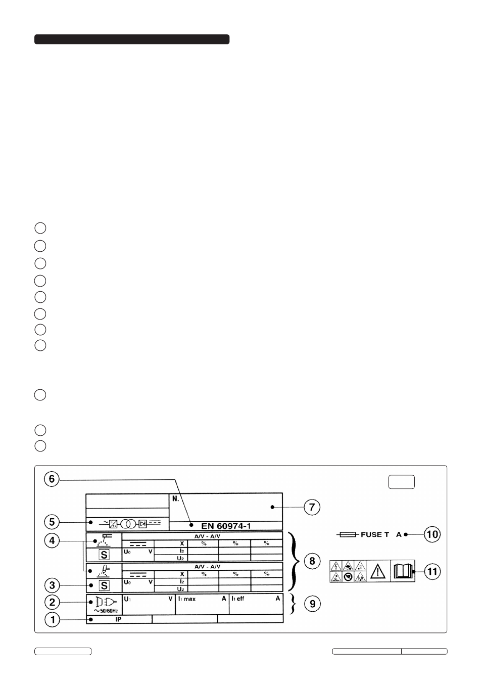
2.3. EXPLANATION OF RATINGS PLATE SYMBOLS (fig.1).
Detailed technical data relative to the performance of the machine is located on the rear of the welder.
Please note that the ratings plate shown below is an example only, intended to assist with the explanations of symbols. To determine the correct technical
values of the machine, please refer to the machine's individual data plate.
1
Case protection grade: IP21. Standard governing the required protection from water ingress and isolation of internal parts from persons and objects.
2
Mains symbol: AC - single-phase supply.
3
Symbol S: Indicates that welding operations may be carried out in areas with greater risk of electric shock (e.g. close to metal masses).
4
Symbol of welding procedure chosen: Manual Arc welding with stick electrode or welding with TIG.
5
Symbol of the main internal parts of the welder: i.e. frequency converter (inverter) - transformer - rectifier.
6
The EUROPEAN standard relating to safety and the construction of Arc welding machines.
7
Manufacturer’s identifying serial number.
8
PERFORMANCE OF THE WELDING CIRCUIT.
UO:
Maximum no-load peak voltage (welding circuit open).
I2 / U2: Current and corresponding normalised voltage that may be supplied from the machine during welding.
X:
Duty cycle: Indicates the time during which machine can supply the corresponding current (same column).
This is expressed as % on the basis of a 10min. cycle (e.g. 60% = 6 min of work, 4 min. break and so on).
A/V-A/V: Indicates the regulation range of the welding current (maximum - minimum) at the corresponding arc voltage.
9
DATA REGARDING THE MAINS.
U1:
Alternating current and power supply frequency of the machine (allowed limits +/-10%).
I1max:
Maximum current absorbed by the line.
I1eff:
Effective current supplied.
10
Size of delayed action fuses to be used to protect the power line.
11
Symbols referring to safety regulations.
fig.1
Original Language Version
TIG160S, TIG180S, TIG200S Issue: 1 - 05/06/13
© Jack Sealey Limited