Fig.10 fig.9, Rating plate, Electromagnetic compatibility – Sealey PP35 User Manual
Page 6
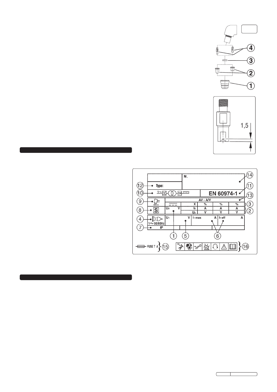
7. RATING pLATE
On the rear of the inverter is the rating plate, giving the following data:
1 - U
0
: Maximum open-circuit voltage.
2 - I
2
, U
2
: Current and corresponding voltage.
3 - X: Duty cycle based on a 10 minute period. 30% indicates
3 minutes cutting and 7 minutes rest, 100% indicates
continuous cutting.
4 - Power Supply: AC, number of phases and frequency.
5 - U
1
: Rated supply voltage.
6 - I
1max
: Maximum RMS current absorbed. I
1eff
: Nominal RMS
current absorbed.
7 - Rating of internal protection provided by casing.
8 - S: Indicates that cutting may be carried out in environments
with a heightened risk of electric shock e.g. very close to
large metallic objects.
9 - Symbol for type of process.
10 - Inverter-transformer-rectifier.
11 - The standard relating to the safety and construction of
welding and cutting equipment.
12 - Equipment model number.
13 - A/V-A/V: Cutting current range and corresponding voltages.
14 - Serial Number. Specifically identifies each inverter.
15 - Rating of delayed action fuse for supply protection.
16 - Symbols referring to safety.
6.3.1.
Cap.
(fig.9.1). Unscrew it manually from the head of the torch. Clean it carefully and check to ensure it is
not damaged (including distortion, burns, cracks). If in any doubt, replace.
6.3.2.
Nozzle
(fig.9.2). If surface is oxidised clean it with extra fine abrasive paper. Check wear of the plasma arc hole and
the inner and outer surfaces. If hole has widened, or nozzle is damaged in any way, replace it.
6.3.3.
Air distribution ring.
(fig.9.3). Make sure there are no burns or cracks and that the air passage holes are not blocked. If any of
these conditions are present or the ring is damaged in any other way, change immediately.
6.3.4.
Electrode.
(fig.9.4).Change the electrode when the depth of the crater formed on the emitter surface is
approximately 1.5mm in depth (fig.10).
NOTE: We recommend that the electrode and nozzle are changed at the same time.
6.4.
Torch body.
Inspect regularly for any breaks, cracks or burns. Keep clean but do not use solvents. Do not use if
damaged but return to authorised service centre.
6.4.1. Reassemble the torch in the correct order which is the reverse of disassembly.
6.4.2. Do not overtighten the electrode as this could damage the torch.
6.4.3. Screw the cap into place and tighten it manually but firmly.
6.5.
Compressed air filter.
The filter, beneath the regulator, removes condensation from the air system, and must be kept clean.
6.5.1. Regularly inspect the filter. If the glass bowl contains water, drain by pushing the drain plug upwards.
6.5.2. When the filter cartridge becomes dirty, replace it.
6.5.3. Clean the filter bowl with soapy water only. Do not use abrasives or solvents.
fig.10
fig.9
8. ELECTROMAGNETIC COMpATIBILITY
8.1.
THIS EQUIPMENT IS IN CONFORMITY WITH THE EUROPEAN STANDARD ON THE ELECTROMAGNETIC COMPATIBILITY
OF ARC WELDING EQUIPMENT AND SIMILAR PROCESSES (e.g. ARC AND PLASMA CUTTING).
8.2.
protection against interference. (E.M.C.) The emission limits in this standard may not, however, provide full protection against
interference to radio and television reception when the equipment is used closer than 30m to the receiving antenna. In special
cases, when highly susceptible apparatus is being used in close proximity, additional mitigation measures may have to be employed
in order to reduce the electromagnetic emissions. At the same time there could occur some potential difficulties in having
electromagnetic compatibility in a non-industrial environment (e.g. in residential areas). Therefore it is most important that the
equipment is used and installed according to the following instructions.
8.3.
Installation and use. The user is responsible for installing and using the equipment according to these instructions.
If electromagnetic disturbances are detected, then it shall be the responsibility of the user of the equipment to resolve the situation
with the technical assistance of the supplier. In some cases this remedial action may be as simple as earthing the circuit (see Note).
In other cases it could involve constructing an electromagnetic screen, enclosing the welding power source and the work, complete
with associated input filters. In all cases the electromagnetic disturbances shall be reduced to the point where they are no longer
troublesome.
Note: The welding/cutting circuit may or may not be earthed for safety reasons. Changing the earthing arrangements should only be
authorised by a person who is competent to assess whether the changes will increase the risk of injury, e.g. by allowing parallel
welding/cutting circuit return paths which may damage the earth circuits of other equipment. Further guidance is given in IEC 974-13
’Arc Welding Equipment - Installation and Use.’
Original Language Version
PP35.V2 Issue: 3 - 15/05/12