Introduction 3. specification 4. assembly – Sealey SUPERMIG130 User Manual
Page 3
IMPORTANT: These instructions contain the information you require to prepare your machine for welding, together with a
maintenance and a troubleshooting section. The instructions are not intended to teach you how to weld. If you have no
experience, we recommend that you seek training from an expert source. MIG welding is relatively easy, but does require a
steady hand and supervised practice on scrap metal, as it is only with continued practice that you will achieve the desired
results.
INTRODUCTION: Features heavy-duty high output transformer and forced-air cooling to ensure the highest level of
performance. Contoured grip, non-live torch is comfortable in the hand, ensuring a steadier weld bead. Includes mini gas
regulator, spool of wire, contact tips 0.6 and 0.8mm and gas cup. Suitable for welding with CO2, Argon or CO2/Argon mix.
Model No: . . . . . . . . . . . . . . . . . . . . . .SUPERMIG130
Welding Current: . . . . . . . . . . . . . . . . . . . . . 30 - 130A
Wire Capacity: - steel. . . . . . . . . . . . . . . . . .0.7 - 5.0kg
Wire Capacity: - aluminium . . . . . . . . . . . . .0.5 - 2.0kg
Duty Cycle:. . . . . . . . . . . . . 100% @ 30A, 60% @ 45A
. . . . . . . . . . . . . . . . . . . . . . . 40% @ 65A, 20% @ 80A
Penetration: - steel. . . . . . . . . . . . . . . . . . . . . . . . 2mm
Penetration: - aluminium . . . . . . . . . . . . . . . . . . . 3mm
Cooling System:. . . . . . . . . . . . . . . . . . . . . . Forced Air
Gas Type:. . . . . . . . . . . . . CO², Argon, CO²/Argon mix
Torch: . . . . . . . . . . . . . . . . . . . . . . . . . . . . . . . .Non-live
Power Input:. . . . . . . . . . . . . . . . . . . . . . . . . 230V 1ph
Absorbed power: . . . . . . . . . . . . . . . . . . . . . . . . 2.8kW
1.3.
GAS SAFETY
Store gas cylinders in a vertical position only and ensure the storage area is correctly secured.
DO NOT store gas cylinders in areas where the temperature may exceed 50°C. DO NOT use direct heat on a cylinder. Always keep gas cylinders cool.
DO NOT attempt to repair or modify any part of a gas cylinder or valve and DO NOT puncture or damage a cylinder.
DO NOT obscure or remove any official labels on a cylinder. Always check the gas identity before use. Avoid getting gas cylinders oily or greasy.
DO NOT lift a cylinder by the cap, guard or valve. Always keep caps and guards in place and close valve when not in use.
4.1. Connecting the gas cylinder (See Section 5.3 regarding gas types)
4.1.1. If the gas cylinder belt is not supplied fitted, thread it through the metal loops in the back panel just below
the handle. Place the lower end of the cylinder into the metal hoop and fasten the belt around the cylinder
as shown in fig.2.
4.1.2. Ensure that the regulator (fig.1) is closed (knob turned fully clockwise) and then screw it onto the cylinder
(finger tight only). Once the regulator has opened the cylinder valve, indicated by the sound of gas
escaping, screw it one full turn further, which is sufficient to seal the cylinder.
WARNING! Excessive tightening of the regulator will over-compress the sealing washer and allow the
gas to leak.
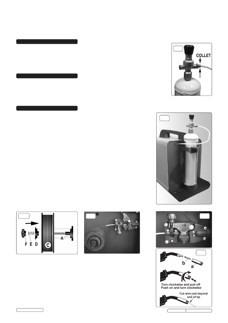
4.1.3. Push the gas tube into the quick connector on the regulator ( to remove tube, press collet in and pull the
tube. (See fig.1). Leave the regulator closed until the welder is fully set up and you are ready to weld.
4.1.4. When you are ready to commence welding switch the machine on and turn the regulator knob halfway for
approx. 2l/min, and all the way for a max. flow of approx. 4l/min.
4.1.5. Always remove the flow regulator after use if the machine is to be stored for some time.
4.2. Fitting the wire reel. The welder is supplied with a mini spool of mild steel wire, but will accept spools of
up to 5kg without modification.
4.2.1. Referring to fig.3, rotate the pressure knob (F) anti-clockwise and remove it from the threaded spindle
together with the spring (E) and the top disc (D). Small reels of wire will run on the spindle itself. The larger
5kg wire reel will run on the larger diameter flange at the base of the reel spindle (A). Place the wire reel
(C) onto the spindle ensuring that the wire withdraws from the top of the spool in a forwards direction
towards the wire feed unit. Place the plastic top disc (D) over the end of the spindle followed by the reel
spring (E). Thread the pressure knob (F) onto the end of the spindle and screw it down clockwise until the
spring is partially compressed. The reel take off pressure should be set to provide a mild braking effect to
prevent overrun where loose coils of wire form on the reel. Do not overtighten this knob as too much
braking will conflict with the wire tension set on the wire drive unit.
4.2.2. Unscrew the wire feed pressure knob and lift the wire feed lever up to the right (fig. 4).
4.2.3. Straighten about 40-50mm of spool wire (do not allow wire to uncoil) and check that the wire end is
smooth and free from burrs. Gently push wire through the plastic guide and through the 6 or 8mm roller
groove and into the wire liner as indicated in fig.4
4.2.4. Hinge down the tension arm and secure with the wire feed knob (fig.5). (See section 4.4 re; wire tension).
fig.4
fig.1
fig.2
fig.3
fig.5
4.3. Feeding the wire through to the torch.
DO NOT touch the torch immediately after welding as it will be hot. Allow to cool and wear protective gloves.
4.3.1. Remove gas cup and contact tip from end of torch as follows:
a) Take torch in left hand with the torch tip facing to the right and grasp gas cup with your right hand.
b) Turn gas cup clockwise only and pull cup out to the right (fig.6).
WARNING! Do not turn gas cup anti-clockwise, as this will damage the internal spring.
c) Unscrew the copper contact tip (right-hand thread) to remove.
4.3.2. Check welder is switched off “O”, (I/O switch, fig.8) and that the earth clamp is away from the torch tip.
Connect the welder to the mains power supply and set the current switches (Max/Min and I/II switches,
fig.8) to ‘Min 1’.
4.3.3. Set the wire speed knob to position 5 or 6 (fig.8) (the higher the number the faster the speed).
4.3.4. Switch the welder on “I”, keep the torch cable as straight as possible and press the torch switch. The wire
will feed through to the torch.
4.3.5. When wire has fed through, switch welder off and unplug from mains.
4.3.6. a)
Thread contact tip over wire and screw into place.
b) Grasp gas cup in right hand, push onto torch head and turn clockwise only.
fig.6
2. INTRODUCTION
3. SPECIFICATION
4. ASSEMBLY
SUPERMIG130 Issue No:2(L) 26/08/14
Original Language Version
© Jack Sealey Limited