Fig.16, Fig.17, Fig.15 – Sealey SUPERMIG255 User Manual
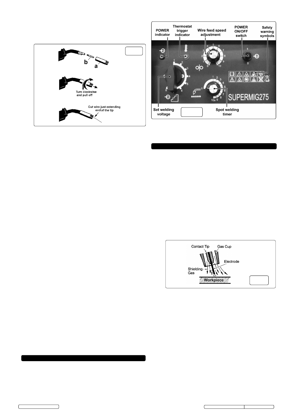
Page 6: Welding principles, Supermig controls
6.3.2 The gas cup is a friction fit onto the torch and can be pulled off with a
twisting action in either direction. Unscrew the copper contact tip using
the maintenance spanner provided across the 6mm flats of the contact
tip. It has a conventional right hand thread.
6.3.3 To feed the wire through to the torch it will be necessary to power up
the welder.
6.3.4 The wire is required to feed through the full length of the torch cable
and if possible it should be laid out straight. If this is not possible the
cable should not be coiled at a diameter of less than 1mtr.
6.3.5 Check that the welder POWER switch is in the 'OFF' position, and that
the earth clamp is isolated and away from the torch tip.
6.3.6 Connect the welder to the mains power supply and set the voltage
switch to “1”.
6.3.7 Using the wire feed speed control, set the knob to position 5 or 6, (the
higher the number the faster the speed). See fig.16. Keep the torch
cable as straight as possible and press the torch switch to feed the wire
through to the torch.
6.3.8 When the wire has fed through, switch welder off, unplug from mains.
6.3.9 Replace contact tip and gas cup. Cut wire so that it is protruding 1/4”
from the cup.
WARNING! During these operations the wire is live and subject to
mechanical stress; therefore, if adequate precautions are not taken the
wire could cause hazardous electric shock, injury and striking of electric
arcs. Do not direct the torch tip towards parts of the body and keep the
torch away from the gas bottle.
6.4 SETTING wIRE TENSION.
IMPORTANT: You must set the correct tension, too little or too much
tension will cause problematic wire feed and result in poor welding.
6.4.1. Tension between rollers is checked by slowing down the wire between
your fingers. If the top feed rollers skid the tension is correct. Use as
low a tension as possible, too high a tension will deform wire and result
in a blown fuse on the printed circuit board. Adjust tension by turning the
pressure knob as shown in fig.9.
6.5
CLUTCh ADJUSTMENT
It is essential that the clutch is adjusted correctly. Once the wire is fed
through the torch, switch on the machine and set the wire speed and
voltage switch to maximum. Depress the torch switch and release
quickly. If spool overruns it indicates that the clutch is too loose. Tighten
the reel clutch adjuster (located in the centre of the reel holder (fig.8),
and test the machine as above until the wire stops over running.
wARNING! DO NOT over tighten the clutch as this will cause
wire feed problems.
6.6
wIRE FEED CONTROL
6.6.1 The wire feed speed can be set using the 'Wire Feed Speed' control
situated on the front panel of each welder. (See fig.16). Use this
rotary control to set the basic wire feed speed required by the welding
parameters of the weld to be executed.
fig.15
fig.16
7.2
SYSTEM pROTECTION
A thermostat is built into the system to protect against overheating.
The indicator light comes on when overheating occurs and cuts off the
power supply; it will reset automatically within a few minutes, after
cooling down.
IMpORTANT.
Should you have no welding experience, we recommend you seek
training from an expert source to ensure your personal health & safety.
You must familiarise yourself with welding applications and limitations,
and specific potential hazards peculiar to welding. Good Mig welding
may be achieved only with continued, supervised practice.
8.1
Mig/Mag welding. (See fig.17). A reel of welding wire is placed on
the reel holder and automatically fed through an insulated liner in the
torch to its tip. The torch consist of a switch, liner, gas hose, and
control cable. The switch activates the wire feed roller and the gas
flow. Releasing the switch stops wire feed and gas flow. The weld
current is transferred to the electrode (the wire) from the contact tip at
the torch end.
Wire speed must be adjusted according to power output. The higher
the current the faster the wire speed. A gas cup fits over the contact
tip to direct gas flow towards the weld ensuring the arc welding
process is shielded from oxidising air contamination (fig.19). The
shielding gas also assists heating of the weld. The torch is connected
to the positive side of a DC rectifier, and negative clamp is attached to
the workpiece.
8. wELDING pRINCIpLES
fig.17
8.2
preparation for welding.
IMPORTANT:
BEFORE YOU COMMENCE, MAKE SURE THE
MACHINE IS SWITCHED OFF AT THE MAINS. IF WELDING A
VEHICLE, DISCONNECT THE BATTERY OR FIT AN ELECTRONIC
CIRCUIT PROTECTOR. ENSURE YOU READ AND UNDERSTAND
THE SAFETY INSTRUCTIONS IN CHAPTER 1.
8.2.1
Connecting the Earth Lead.
Connect the earth lead as described in section 5.5.
To ensure a complete circuit, the earth lead clamp must be securely
attached to the workpiece that is to be welded.
a) Best connection is obtained by grinding the point of contact on the
workpiece before connecting clamp to the workpiece.
b) The weld area must also be free of paint, rust, grease, etc.
c) If welding a vehicle, disconnect vehicle battery or fit an “Electronic
Circuit Protector” to battery, (available from your Sealey dealer).
8.2.2
The wire feed rate rotary controls are used to set the speed of the wire
feed. In principle, the lower the amperage number the slower the wire
speed.
8.3
Gas types and their use.
Welding mild steel with CO² gas is appropriate for most welding tasks
where spatter and high build up of weld do not pose a problem. To
achieve a spatter free and flat weld however, as a guideline, use an
Argon/CO² mixture. To weld aluminium use: Argon gas or Argo-
Helium mixture, 0.8mm Contact Tip, 0.8mm Aluminium Wire,
(MIG/2/KAL08)
Liner (red) Aluminium.
6.3
FEEDING wIRE ThROUGh TO ThE TORCh.
6.3.1 Before feeding the wire through to the torch, the gas cup and contact tip
should be removed as shown in fig.15.
7. SUpERMIG CONTROLS
7.1
CONTROLS - SUpERMIG 255 & 275
7.1.1 Fig.16 illustrates the main panel controls for both
Supermig255 &
Supermig275. The control functions are identical for both models.
Original Language Version
© Jack Sealey Limited 2013
SUPERMIG255, SUPERMIG275 Issue: 2 (SP)- 28/08/13