Specification, Operation – Sealey TA102 User Manual
Page 2
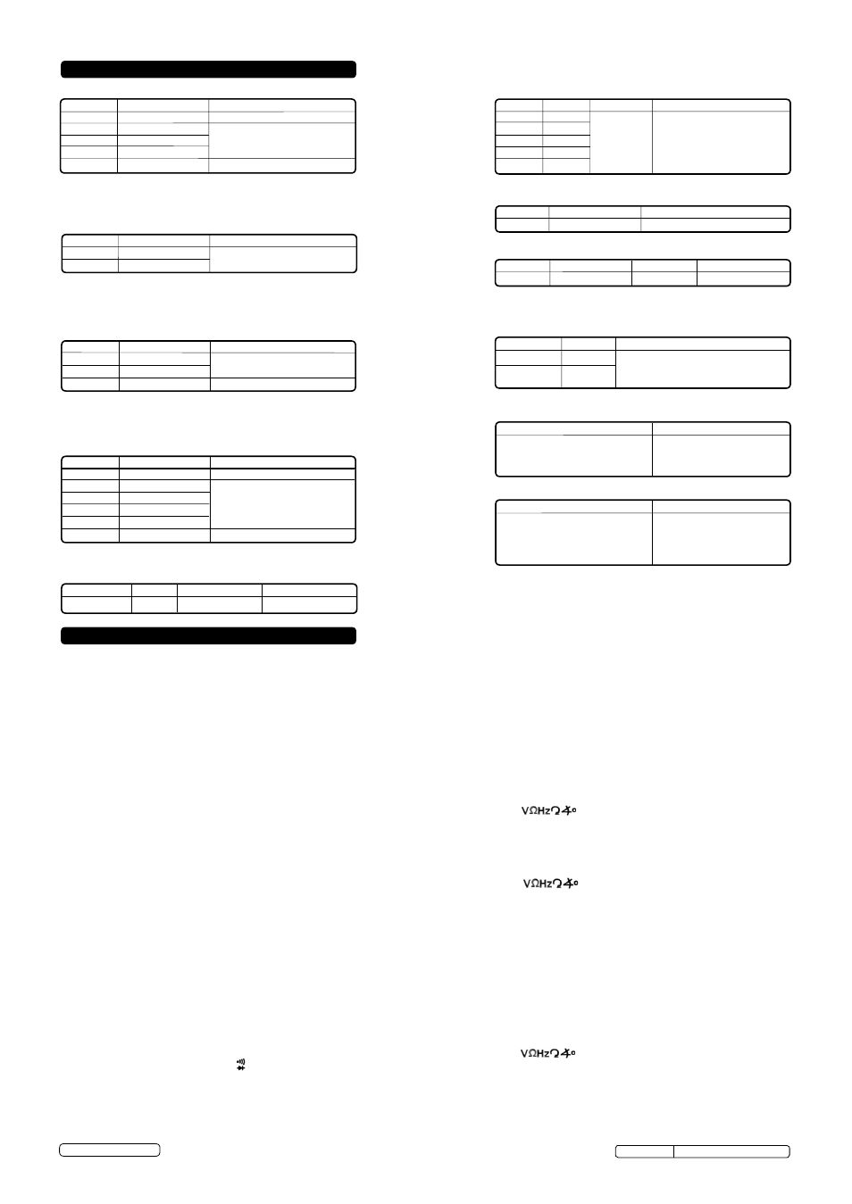
3. SPECIFICATION
Range Resolution Accuracy
200mV 100µV
± (0.5% + 5)
2V 1mV
20V
10mV
± (0.8% + 5)
200V 100mV
1000V
1V
± (1.0% + 5)
Range Resolution Accuracy
20mA 10µA
± (1.8% + 3)
200mA 100µA
10A
10mA
± (3.0% + 7)
DC voltage
Input Impedance: 1MΩ for all ranges.
Overload protection: 1000V DC/AC rms
(for 200mV range) 250V AC rms
DC Current
Overload Protection: F 250mA L 250V (range 10A unfused).
Maximum Input Current: 10A (less than 15 seconds).
Maximum Voltage Drop: 200mV.
Indication: Average (rMS of sine wave).
Range Resolution Accuracy
200Ω
0.1Ω
± (1.0% + 5)
2kΩ
1Ω
20kΩ
10Ω
± (0.8% + 5)
200kΩ
100Ω
2MΩ
1kΩ
20MΩ 10kΩ
± (2.0% + 7)
Resistance
Range
Resolution
Accuracy
20kHz
10Hz
± (1.5% + 5)
Frequency
Range Resolution Accuracy
-20°C~750°C 1°C -20~0°C(-4°F~32°F)±(6.0% +6)
0~400°C(32°F~752°F)±(1.0% +7)
-4°F~1382°F 1°F 400~750°C(752°F~1400°F)±(2.0%+7)
Temperature
Range Scope (RPm) Resolution Accuracy
rPM
180~10000 1*10rPM ± (2.5% + 5)
Tachometer
Description
test condition
Cylinder Range
Resolution Accuracy
3CYL
0~120.0°
4CYL 0~90.0°
5CYL
0~72.0° 0.1°
± (2.5% + 5)
6CYL 0~60.0°
8CYL 0~45.0°
Dwell Angle
Diode test
Range
hFE Test Current Test voltage
PNP and NPN 0~1000 Ib=10µA Vce = 3V
Transistor hFE test
Audible Continuity Test
Range Resolution Accuracy
200V
100mV
± (1.0% + 5)
750V
1V
± (1.2% + 5)
AC voltage
Input Impedance: About 450kΩ for all ranges.
Frequency range: 40Hz~400Hz
Indication: Average (rMS of sine wave).
Overload protection: 1000V DC/AC rms
If the resistance of the circuit
under test is lower than 30Ω,
the audible warning will sound.
Open circuit voltage is
approximately 3V.
Description
test condition
the approximate forward
voltage of the diode under test
will be displayed on the LCD.
the forward DC current is
approximately 1mA, the
reversed DC voltage is
approximately 3V.
4. OPERATION
WARNING! Ensure that you read, understand and apply the safety and operational instructions before connecting the analyser. Only when you are sure
that you understand the procedures is it safe to proceed with testing.
WARNING! risk of electrocution. High voltage circuits, both AC and DC are very dangerous and should be measured with great care.
Operating temperature range 0°C to 40°C.
Remember to turn off the analyser when measurement is completed.
NOTE: If '1' appears in the display during a measurement, the value exceeds the range you have selected. Select a higher range.
NOTE: On some low AC and DC ranges, with the test leads not connected to a device, the display may show a random fluctuating reading. this is
normal and is caused by the high input sensitivity. the reading will stabilise and give a correct measurement when connected to a circuit.
4.1.
Data Hold Button
4.1.1. the data hold function allows the analyser to freeze a measurement reading for later reference.
4.1.2. Press the data hold button once to freeze the reading in the display. the indicator 'H' will appear in the display.
4.1.3. Press the data hold button again to return to normal operation.
4.2.
AC voltage measurement
4.2.1.
Insert the black test lead into the negative COM socket and the red test lead into the positive
socket.
4.2.2. turn the function dial to the appropriate AC voltage setting as required and switch the analyser on (see ranges above). If the voltage range to be
measured is not known, set to the highest range setting, and then select to the correct range when first reading is taken, until a satisfactory resolution is
obtained.
4.2.3. Connect the test leads to the circuit under test and read the voltage on the display.
4.3.
DC voltage measurement
4.3.1.
Insert the black test lead into the negative COM socket and the red test lead into the positive socket.
4.3.2. turn the function dial to the appropriate DC voltage setting as required and switch the analyser on (see ranges above). If the voltage range to be
measured is not known, set to the highest range setting, and then select to the correct range when first reading is taken, until a satisfactory resolution is
obtained.
4.3.3. Connect the test leads to the circuit under test and read the voltage on the display.
4.4.
DC Current measurement
WARNING! Do not make current measurements at 10A for longer than 15 seconds in every 15 minutes. Exceeding this may cause damage to
the analyser and test leads.
4.4.1. Insert the black test lead into the negative COM socket, and the red test lead into the
positive mA socket (or the positive 10A socket for currents from
200mA
to
10A).
4.4.2. turn the function dial to the appropriate setting as required (see ranges above). If the current range to be measured is not known, set to the highest
range setting, and then select to the correct range when the first reading is taken, until satisfactory resolution is obtained.
4.4.3. Connect the test leads in series with the circuit under test and read the current on the display.
4.5.
Diode measurement
4.5.1. Insert the black test lead into the negative COM socket and the red test lead into the positive socket.
4.5.2. turn the function dial to the position and switch the analyser on.
4.5.3. Connect the red test lead to the anode of the diode, and the black test lead to the cathode of the diode.
4.5.4. the approximate forward voltage drop of the diode will be displayed. If the connection is reversed, a fig “1” will be displayed.
Open circuit voltage: less than 2.8V
Overload protection: 250V DC/AC rms
© Jack Sealey Limited
tA102 Issue No: 4(I) - 16/06/14
Original Language Version