Sealey VS021 User Manual
Pneumatic brake bleeder, Vs021.v3, Instructions for
3.1. Brake bleeding procedure.
Refer to the vehicle manufacturer’s instructions for brake bleeding and wheel sequence before proceeding. If no
specific instructions from the vehicle manufacturer exist, follow the instructions detailed below.
WARNING! Familiarise yourself with the hazards of brake fluid - read manufacturers instructions on the
container. Do not touch the vehicle’s brake pedal whilst bleeding the brakes.
3.1.1. Remove the cap of the vehicle’s brake fluid reservoir. If the fluid level is not at maximum top it up.
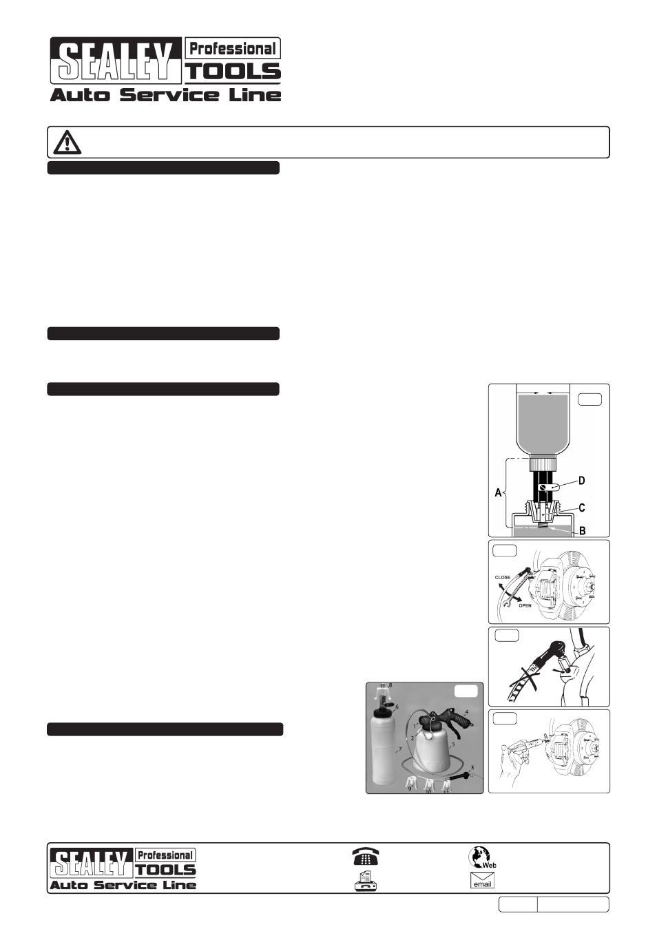
3.1.2. Remove the cap assembly (fig.1-A) from the replenishment bottle and invert it within the neck of the reservoir as shown
in fig.1. The threaded outlet ‘B’ must be immersed in the brake fluid. If it is not, rotate the three legged moulding ‘C’
clockwise towards the valve ‘D’ until sufficient thread is exposed to allow the outlet to be immersed in the brake fluid.
3.1.3. Ensure the valve is closed as shown in fig.1-D.
3.1.4. Fill the replenishment bottle just under half full with new brake fluid and screw the cap assembly back down onto the
bottle. Invert the bottle over your container of new brake fluid and open the valve so that the fluid level begins to drop
towards the level marked on the bottle. As soon as the level mark is reached close the valve.
3.1.5. Place the bottle into the neck of the vehicle brake fluid reservoir as shown in fig.1. and open the valve. As the brakes
are bled the fluid level in the resevoir will begin to drop and expose the bottle outlet. Brake fluid will begin to flow from
the replenishment bottle. Once the level in the reservoir has risen sufficiently to cover the outlet the flow will
automatically stop.
3.1.6. Connect the brake bleeder to a suitable compressed air unit.
3.1.7. Mount the black rubber pipe onto the brake nipple on the first wheel and open the nipple about ¼ of a turn (fig.2).
3.1.8. Activate the brake bleeder’s trigger. The vacuum created will draw the brake fluid from the vehicle’s brake system.
3.1.9. Continue to bleed the system until there are no air bubbles visible in the clear tube (fig.3).
3.1.10. Close the brake nipple (fig.2).
3.1.11. Remove the rubber pipe from the brake nipple.
3.1.12. Depress the trigger to clear brake fluid from the clear pipe.
3.1.13. Repeat the process at each wheel in turn.
3.2. Changing the brake fluid
3.2.1. Repeat the brake bleeding procedure as described above. As the fluid is being completely changed regularly check the
level in the replenishment bottle.
3.2.2. When new fluid can be seen in the clear tube tighten the brake nipple.
3.2.3. Repeat this procedure at every wheel.
When brake bleeding and/or fluid changing is complete, test the action of
the brake pedal to ensure that the brakes are working correctly, before driving
the vehicle on the road.
3.2.4. Apply copper grease to the brake bleeding nipples before and after the brake
bleeding procedure to eliminate the possibility of seized or broken nipples when the
brakes are next bled (fig.4).
Keep this product in good working order and condition, take immediate action to repair or replace damaged parts.
Use approved parts only. Unapproved parts may be dangerous and will invalidate the warranty.
Keep children and unauthorised persons away from the work area.
Keep work area clean and tidy and free from unrelated materials.
Ensure the work area has adequate lighting.
DO NOT use the kit to perform a task for which it is not designed.
DO NOT allow untrained persons to use the kit.
DO NOT use whilst under the influence of drugs, alcohol or intoxicating medication.
After use, clean equipment and store in a cool, dry, childproof area.
Dispose of waste liquids in accordance with local authority regulations.
WARNING! DO NOT pollute the environment by allowing uncontrolled discharge of fluids.
Always read and comply with the warnings on the brake fluid container.
Wear eye protection and keep skin contact to a minimum. If brake fluid enters eyes rinse with plenty of water and seek medical advice. If swallowed seek
medical advice immediately.
WARNING! Brake fluid is flammable - keep away from sources of ignition, including hot surfaces e.g. exhaust manifold.
WARNING! Brake fluid will damage paintwork. Any spillage should be flushed with water immediately.
The VS021.V3 pneumatic brake bleeder enables simple, one man operation using a standard workshop air supply ( 90 to 120psi ). Quick clean and efficient
operation without requiring specialised brake reservoir caps. Draws fluid from the brake nipple enabling brake bleeding or full replacement of fluid in the system.
Inlet air pressure: . . . . . . . . . 6 - 12bar (87 - 174psi)
Container capacity:. . . . . . . . . . . . . . . . . . . . 1.0 litre
Air consumption:. . . . . . . . . . . . . . . . . . . . 180ltr/min
Vacuum: . . . . . . . . . . . . . . . . . . . . . . . . . . . . . . 60%
Thread connection:. . . . . . . . . . . . 1/4”BSP (female)
fig.4
fig.5
1. sAfeTy INsTRuCTIONs
2. INTRODuCTION & speCIfICATION
3. OpeRATION
ITeM pART NO. DesCRIpTION
1.
VS021.01
FIlTER
2.
VS021.02
lID ASSy
3.
VS021.03
hOSE ASSy
4.
VS021.04
TRIggER ASSy
5.
VS021.05
COnTAInER
6.
VS021.06
lID
ITeM pART NO. DesCRIpTION
7.
VS021.07
COnTAInER
8.
VS021.08
ADAPTOR A
9.
VS021.09
ADAPTOR B
10.
VS021.10
ADAPTOR C
11.
VS021.11
ADAPTOR D
4. pARTs (fIG.5)
InSTRUCTIOnS FOR:
pNeuMATIC BRAke BleeDeR
MODEl nO:
vs021.v3
Thank you for purchasing a Sealey product. Manufactured to a high standard this product will, if used according to these instructions and properly maintained, give you years
of trouble free performance.
IMPORTANT: pleAse ReAD THese INsTRuCTIONs CARefully. NOTe THe sAfe OpeRATIONAl ReQuIReMeNTs, WARNINGs, AND
CAuTIONs. use THIs pRODuCT CORReCTly, AND WITH CARe fOR THe puRpOse fOR WHICH IT Is INTeNDeD. fAIluRe TO DO sO
MAy CAuse DAMAGe AND/OR peRsONAl INJuRy AND WIll INvAlIDATe THe WARRANTy.
fig.3
fig.2
fig.1
Original Language Version
NOTE: It is our policy to continually improve products and as such we reserve the right to alter data, specifications and component parts without prior notice.
IMpORTANT: no liability is accepted for incorrect use of this equipment.
WARRANTy: guarantee is 12 months from purchase date, proof of which will be required for any claim.
INfORMATION: For a copy of our latest catalogue and promotions call us on 01284 757525 and leave your full name and address, including postcode.
01284 757500
www.sealey.co.uk
01284 703534
sole uk Distributor, sealey Group,
Kempson Way, Suffolk Business Park,
Bury St. Edmunds, Suffolk
IP32 7AR
VS021.V3 Issue no.2 - 28/03/12