Sealey PFT/02 User Manual
Fig.2 fig.4 fig.3, Fig.1 fig.5
WARNING! Before using the flaring kit, ensure that you
have read and understood the Safety Instructions
in Section 1.Ensure you are familiar with the various types
of flares before using this equipment.
3.1. Preparation of the Brake Pipe.
3.1.1. The end of the pipe must be cut square
3.1.2. The outside edge of the pipe must be chamfered approx
0.25mm X 45º
3.1.3. The bore of the pipe must be de-burred.
3.1.4. If the pipe is plastic covered, this must be removed for 3mm
from the end of the pipe to be flared. Ensure the pipe is not
scored or any metal removed during the operation.
DO NOT
use abrasive cloth. Blow any debris from the pipe after
flaring.
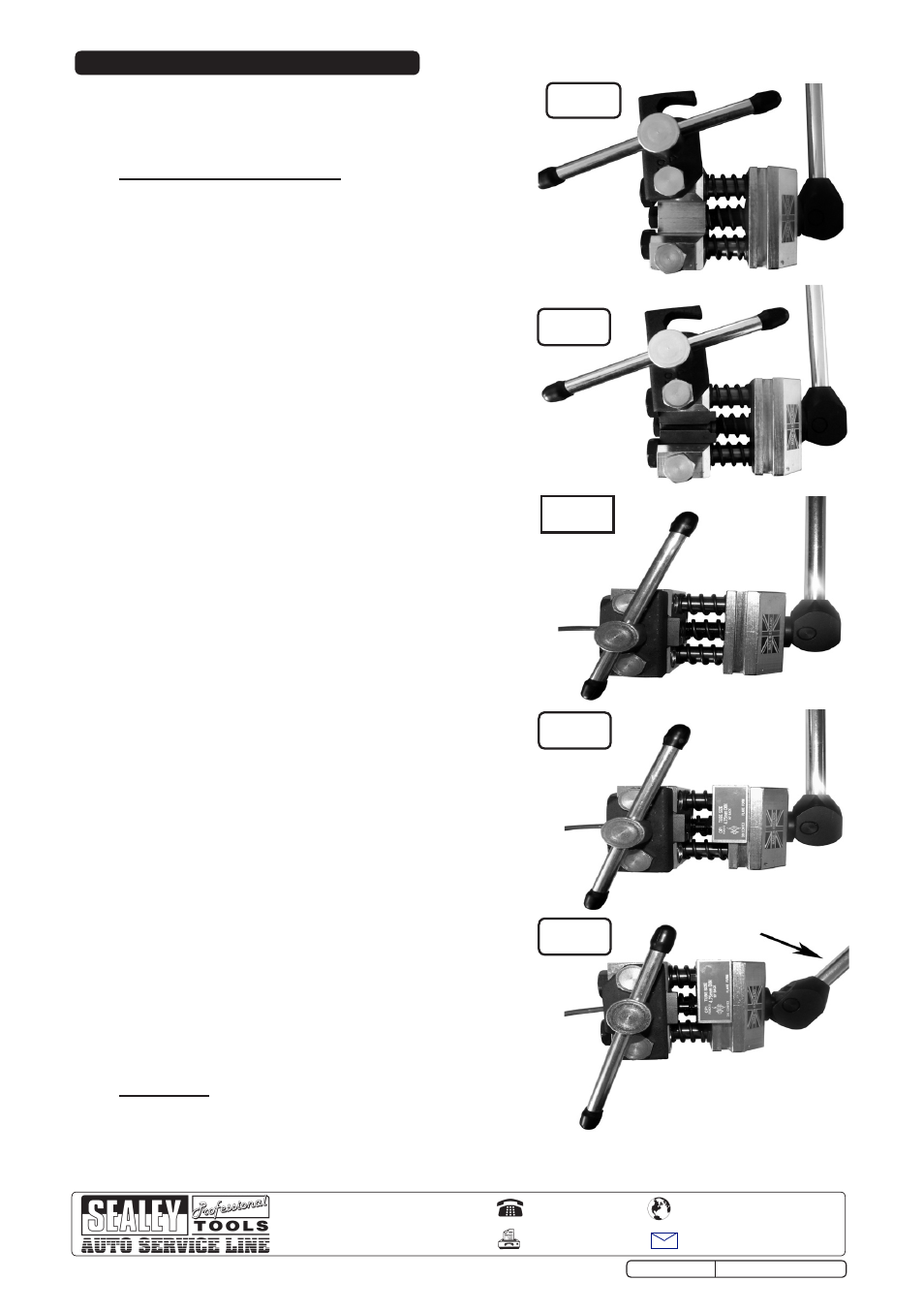
3.2. Clamp the tool in a suitable bench mounted vice. Assemble
the lever onto the cam as shown (Fig.1). Loosen the
clamping screw to allow the clamp to swing open.
3.3. The pipe end to be flared must be cut clean and square and
be de-burred. Use a pipe or tube cutter (available from your
Sealey dealer).
3.4. Consult Chart 1 and select the punch holder containing the
punches and the die specified to produce the required flare.
Place the die into the cavity as shown with the split line
horizontal and the counterbore towards the operating lever
(Fig.2).
3.5. After the pipe has been prepared as instructed above,
ensure the tube nut is fitted to the pipe. Pass the pipe
through the rear of the die until the prepared end is flush
with the front face of the die. Ensure that both halves of the
die are contacting the die stops. Swing the locking plate into
position and tighten the clamping screw. Check that the
position of the pipe and die are still correct (Fig.3).
3.6. Fit the specified punch and holder into the mating groove in
the sliding portion of the tool with the required punch of the
first operation facing and in line with the pipe (Fig.4).
3.7. Pull the lever to engage the punch into the end of the brake
pipe and continue to form the flare until a solid resistance is
felt (Fig.5). Return the handle to the original position to
withdraw the punch. If the required flare calls for a second
operation in Chart 1, slide the correct Op.2 punch in line
with the brake pipe.Operate the lever to complete the form
of the flare.
Return the lever to the original position to withdraw the
punch. Release the clamping screw and swing the clamp
open and remove the dies with the pipe. If necessary a
gentle tap on a suitable surface will release the dies from
the pipe.
Check the quality of the flare to ensure the pipe did not
move during the flaring.
IMPORTANT
The punches and dies supplied for this tool must only be
used with this equipment.
3. OPERATING INSTRUCTIONS
fig.2
fig.4
fig.3
NOTE: It is our policy to continually improve products and as such we reserve the right to alter data, specifications and component parts without prior notice.
IMPORTANT: No liability is accepted for incorrect use of this equipment.
WARRANTY: Guarantee is 12 months from purchase date, proof of which will be required for any claim.
INFORMATION: For a copy of our latest catalogue and promotions call us on 01284 757525 and leave your full name and address, including postcode.
Original Language Version
PFT/02.V3 Issue: 1 - 07/04/11
01284 757500
01284 703534
Sole UK Distributor, Sealey Group,
Kempson Way, Suffolk Business Park
,
Bury St. Edmunds, Suffolk,
IP32 7AR
www.sealey.co.uk
Web
fig.1
fig.5