Sealey HBS97 User Manual
Universal headlamp beam setter, Instructions for, Models
HBS97.V2, HBS971 - 2 - 290806
3. WORKING SURFACE
3. 1. Position the vehicle on the designated headlamp aim standing area.
3. 2. When positioning the HBS ensure the floor is perfectly even and level.
3. 3. If this is not possible the vehicle and HBS must be on the same slope, which must not exceed 0.5º.
3. 4. Headlights must not be checked where surfaces exceed 0.5º angle. (See fig 3A.).
OK
fig 3A.
NO
NO
0.5
0
MAX
INSTRUCTIONS FOR:
UNIVERSAL HEADLAMP BEAM SETTER
MODELS:
H B S 9 7 . V 2 & H B S 9 7 1
Thank you for purchasing a Sealey Product. Manufactured to a high standard this product will, if used according to these instructions
and properly maintained, give you years of trouble free performance.
4. 1. Straighten vehicle wheels.
4. 2. Check the tyre pressure.
4. 3. Ensure the headlights are clean and dry.
4. 4. If the vehicle is fitted with manual or electric headlamp levelling devices, ensure these are set up for vehicle with normal load.
4. 5. Remove anything which could alter the vehicles position, i.e. Snow, Ice, Mud, etc.
4. VEHICLE PREPARATION
IMPORTANT
PLEASE READ THESE INSTRUCTIONS CAREFULLY. NOTE THE SAFE OPERATIONAL REQUIREMENTS, WARNINGS AND CAUTIONS.
USE THIS PRODUCT CORRECTLY AND WITH CARE FOR THE PURPOSE FOR WHICH IT IS INTENDED. FAILURE TO DO SO MAY CAUSE
DAMAGE OR PERSONAL INJURY, AND WILL INVALIDATE THE WARRANTY. PLEASE KEEP INSTRUCTIONS SAFE FOR FUTURE USE.
The SEALEY HEADLAMP BEAM SETTERS, HBS97.V2 & HBS971 are supplied with a rotating column, mirror and visor. The HBS97.V2 has
the addition of a rail set. Either HEADLAMP BEAM SETTER may be used for checking headlights on cars, motorcycles and commercial vehicles.
The HBS97.V2 is approved by VOSA for testing all vehicle classes with the appropriate set of rails (Excluding HGV).
SPECIFICATIONS:
Height . . . . . . . .1520/1770mm
Maximum height of beam measurement . . . . . . .1410mm
Width . . . . . . . . . . . . . .610mm
Minimum height of beam measurement . . . . . . . . 240mm
Length . . . . . . . . . . . . .610mm
Focal Length . . . . . . . . . . . . . . . . . . . . . . . . . . . .500mm
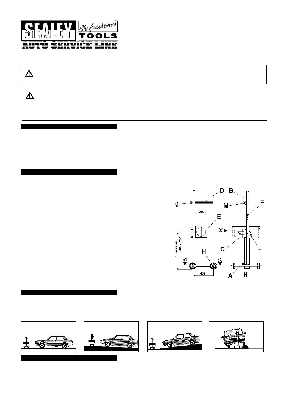
A BASE
B COLUMN
C VERTICAL SLIDING SYSTEM
D MIRROR-VISOR
E OPTICAL SYSTEM
F COLUMN LOCK PEDAL
2. 0
Place large metal washer over spigot at base of column B.
2. 1
Insert column spigot into bearing in base A and retain with socket cap bolt and
washer provided.
2. 2. Attach mirror-visor D to the rotating metal friction plate at the top of the column
using the two socket cap bolts provided.
2. 3. Fit the optical system E to the vertical - sliding system using an M8 bolt in both the
top and bottom holes.
2. 4 If the unit is to run on rails these need to be fixed to the floor of the test bay with
low profile fixings that will not interfere with the movement of the wheels.
2. 5 To ascertain the correct positions for the rails place a typical vehicle in the test bay
and follow the test procedure without rails. When the unit is correctly positioned for
one headlamp mark the wheel positions on the floor including a longitudinal
centre line. Roll the unit over to the other headlamp, check the alignment, and
mark the floor again.
2. 6
Place the rails loose on the floor using the markings made and put the unit on
them. Roll the unit from one lamp to the other and recheck the alignment. When
satisfied that all is correct fix the rails to the floor.
2.7
HBS97.V2 is approved by VOSA for class I,II,III and IV as delivered, and by
purchasing HBS97E Rail Extensions the unit is also suitable for Class V, VI,VII.
For testing classes I, II, III and IV the rails may be surface mounted. We
recommend the rails be recessed into the floor for all other vehicle testing classes.
1. DESCRIPTION
2. ASSEMBLING THE BEAM SETTER
GENERAL RULES. Read instruction manual carefully before using the headlight beam tester.
TO AVOID DAMAGE ENSURE THE FOLLOWING IS STRICTLY APPLIED.
DO NOT allow unqualified persons to operate this device.
DO NOT use this device in direct sunlight.
DO NOT splash the unit with water or any other liquid.
DO ensure the work area is well ventilated.
DO ensure that there is good lighting
DO put the handbrake on.
DO avoid sudden changes in temperature.
DO avoid sudden vibration.