Operation 4. contents – Sealey BT2003 User Manual
Page 2
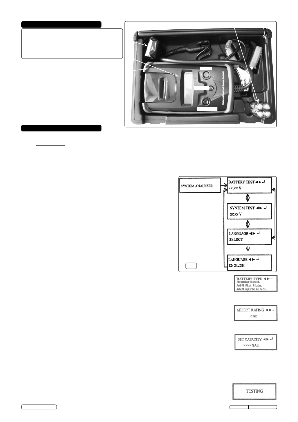
fig.1
5.3.
BATTERY TEST
5.3.1. With battery test screen displayed press eNTeR.
5.3.2. use the
< (forward) and > (back) buttons to select the battery type: Regular Liquid, AGM Flat Plate, AGM
Spiral, Gel.
Press eNTeR to confirm choice.
5.3.3. use the
< (forward) and > (back) buttons to select the battery rating: SAe, eN, IeC, DIN or JIS. )
Press eNTeR to confirm.
5.3.4. use the
< (forward) and > (back) buttons to input the battery capacity.
CCA:
DIN: 25 - 1300
eN: 40-2100
IeC: 30 - 1500
JIS: By battery type
SAe: 40 - 2000
Press eNTeR to begin test.
5.3.5. Test Battery for 1 second.
5.2.
DISPLAY GENERAL
By pressing the
< (forward) and > (back) buttons the display will cycle
through the options. Press
ENTER button when the option you require is
displayed.
5.2.1.
System Analyser will display initially and then automatically switch to
Battery Test. (fig.1)
5.2.2. use the
< (forward) and > (back) buttons to cycle between System Test,
Language Select, and Battery Test. (fig.1)
WARNING! ensure that you read, understand and apply the safety and operational instructions before connecting the tester clamps to
the battery. only when you are sure that you understand the procedures is it safe to proceed with the testing process.
5.1.
PREPARATION
WARNING!
Ensure that the vehicle, or battery, is in a well ventilated area before starting to test.
5.1.1. Check battery casing for cracks or leakage. If damage is found
DO NOT test, replace battery.
5.1.2. Clean battery terminals.
5.1.3. If possible, check electrolyte levels and top-up with distilled water as necessary.
5.1.4. unless otherwise specified tests are carried out with
all electrical items
switched off.
Leaving any items switched on (boot light, interior light, etc.) can result in misdiagnosis.
5.1.5. Confirm that the 4 x AA Batteries (supplied) are correctly fitted (fig.2) in the
compartment in the base of the tester. Batteries are best fitted with the rubber
jacket removed (fig.3).
Note that nothing will be seen on the display until
the tester is connected to a vehicle battery.
5.1.6.
Connect the red clamp to the positive (+) battery terminal and the black clamp
to the negative (-) terminal. When the internal battery becomes discharged the
display will read
INTERNAL BATTERY LOW.
5.1.7. If there is a poor connection the display will read
CHECK CLAMPS, otherwise
the display will read either
BATTERY TEST or SYSTEM TEST or LANGUAGE.
5.1.8. Paper Load: open the clear cover. Insert the paper in the feeder, it will
automatically feed into the printer.
5. OPERATION
4. CONTENTS
Item......... Description.............................................. Qty
1.............. Analyser/Lead/Crocodile Clips................ 1-set
2.............. Rubber Jacket......................................... 1
3.............. Printer Rolls............................................. 2
4.............. "AA" 1.5v Batteries.................................. 4
5.............. Blow Mould Carry Case...........................1
2
4
3
5
1
BACK
FoRWARD
eNTeR
BT2003.V5 Issue: 1 - 28/11/14
Original Language Version
© Jack Sealey Limited