Operation 6. maintenance – Sealey CV2030 User Manual
Page 2
Original Language Version
CV2030 Issue: 1 - 15/08/14
© Jack Sealey Limited
6.1.
Always keep the plastic adaptors clean and free of oil and grease. Clean them regularly with a non-aggressive cleaner.
5.1.
Follow the manufacturer's instructions for the removal, if required, of the device or hose to be tested. Use gloves and arm protection if
the system is known to be hot.
5.2.
Connect an air line with known air pressure to the regulator of the tester with the ball valve shut (operating lever at 90° to hose axis).
IMPORTANT! Regulate air pressure in tester to 25psi maximum. Refer to manufacturer's manual relating to the maximum air
pressure of the turbo or other system being tested. Over pressurisation may damage system components.
5.3.
Method
5.3.1.
Select the correct air inlet adaptor and plug adaptor by first measuring the aperture diameter and then couple the tester hose to the
selected air inlet adaptor.
5.3.2.
Set regulator of tester to 5psi to check for large leaks with valve shut (operating lever at 90° to hose axis).
5.3.3.
Plug the exit aperture of the system with the plug adaptor.
5.3.4.
Connect the inlet adaptor set at 5psi to the entry aperture of the system.
5.3.5.
Open valve fully (operating lever in line with hose axis) to check for leaks and or pressurisation up to pre-set (5psi). If a leak is found, by
listening or if the pointer falls. Repair the leak and retest.
5.3.6. If no leaks are evident, regulate pressure to 10psi and check for leaks and or pressurisation up to pre-set (10psi). If a leak is found, by
listening or if the pointer falls, it indicates that the system has a leak resulting in loss of pressure. Repair the leak and retest.
5.3.7. If no leaks evident, regulate pressure to a maxmum of 15psi or to the manufacturer's maximum pressure and retest. If a leak is found, by
listening or if the pointer falls. Repair the leak and retest. If the gauge pointer remains stationary for one minute it will indicate that the
system is in good working order.
5.3.8.
Release pressurised system by rotating the ball valve lever to align with hose axis.
5.3.9. Disconnect the quick coupler, clean and return all items to carry case.
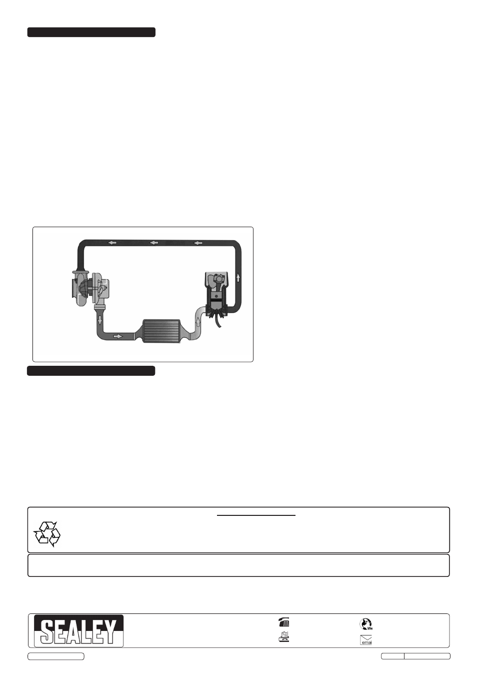
Intercooler
coil
Turbo
Engine
System schematic
NOTE: It is our policy to continually improve products and as such we reserve the right to alter data, specifications and component parts without prior notice.
IMPORTANT: No liability is accepted for incorrect use of this product.
WARRANTY: Guarantee is 12 months from purchase date, proof of which will be required for any claim.
INFORMATION: For a copy of our latest catalogue and promotions call us on 01284 757525 and leave your full name and address, including postcode.
01284 757500
01284 703534
Sole UK Distributor, Sealey Group,
Kempson Way, Suffolk Business Park
,
Bury St. Edmunds, Suffolk,
IP32 7AR
www.sealey.co.uk
Parts support is available for this product. To obtain a parts listing and/or diagram, please log on to www.sealey.co.uk,
[email protected] or telephone 01284 757500.
Environmental Protection
Recycle unwanted materials instead of disposing of them as waste. All tools, accessories and packaging should be sorted,
taken to a recycling centre and disposed of in a manner which is compatible with the environment.
When the product becomes completely unserviceable and requires disposal, drain off any fluids (if applicable)
into approved containers and dispose of the product and the fluids according to local regulations.
5. OPERATION
6. MAINTENANCE