Sealey BC301 User Manual
Pro trainer - bicycle, Bc301
Maintain the trainer in good condition, replace or repair damaged parts. Use recommended parts only. Non authorised parts may be
dangerous and will invalidate the warranty.
Before use ensure that all nuts and bolts are tight and that moving and clamping parts are in good working order.
Place the Pro Trainer on a sound level surface offering adequate working clearance for its function. Keep the area clean, tidy and free from
unrelated materials. Ensure there is adequate lighting.
Remove ill fitting clothing. Remove ties, watches, rings, and other loose jewellery, and contain long hair.
Keep children, pets and unauthorised persons away from the “workout” area.
7
Hard braking whilst using the Pro Trainer may cause excessive wear on cycle tyres and the trainer.
7
Never touch the wheels whilst they are in motion.
7
Never let go of the handlebars.
Always properly warm up before working out. Consult your physician before starting any exercise regime.
NOTE this Pro Trainer is not intended for use by persons (including children) with reduced physical, sensory or mental capabilities or lack of
experience and knowledge, unless they have been given supervision or instruction concerning the use of the appliance by a person
responsible for their safety. Children should be supervised to ensure they do not play with the appliance.
When not in use store the stand in a safe, dry, child proof area.
DO NOT exceed maximum load of 150kg.
Perfect for beginners or professionals who want to train all year round. Converts outdoor bicycle into an indoor trainer. Features a magnetic flywheel
unit with seven resistance settings, foldable frame, non-slip feet and quick release levers. Includes replacement hub skewer and front wheel block.
Model No: ........................................................................................BC301
Wheel Sizes: ........................................................................ 26” and 700C
Max Load ......................................................................................... 150kg
BC301 Issue: 2(I) - 16/12/14
© Jack Sealey Ltd
Original Language Version
INSTrUCTIoNS For:
PRO TRAINER - BICYCLE
ModEL No:
BC301
IMPORTANT: PLEASE READ THESE INSTRUCTIONS CAREFULLY. NOTE THE SAFE OPERATIONAL REQUIREMENTS, WARNINGS & CAUTIONS. USE THE PRODUCT
CORRECTLY AND WITH CARE FOR THE PURPOSE FOR WHICH IT IS INTENDED. FAILURE TO DO SO MAY CAUSE DAMAGE AND/OR PERSONAL INJURY AND WILL
INVALIDATE THE WARRANTY. KEEP THESE INSTRUCTIONS SAFE FOR FUTURE USE.
Thank you for purchasing a Sealey product. Manufactured to a high standard, this product will, if used according to these
instructions, and properly maintained, give you years of trouble free performance.
read instruction
manual
1. SAFETY
2. INTRODUCTION
3. SPECIFICATION
4. CONTENTS
1
11
4
6
3
2
13
9
8
10
12
7
Item
No
description Qty
1 “A”
Frame 1
2
Flywheel mechanism c/w cable
1
3
Quick release rod sub assembly
1-set
4
Clamp pedal sub assembly
1-set
5
Clamp cam follower
1
6
Pivot bolt 82 long (M8)
1
7
recessed plastic washer
2
8
C’sk screw M6 x 12
2
9
Stiff nut M8
2
10
Plain washer Ø8
3
11
open ended spanner 13/14 A/F
2
12
Hexagon key 4mm
1
13
Front wheel anti slip stand
1
fig.1
NOTE:
For best results make sure that your tyres are inflated to the maximum pressure allowed for your tyre. The maximum pressure will be
found moulded into the side wall of the tyre.
NOTE: To avoid a permanet “memory set” in the cycle tyre, when not using your Pro Trainer, either remove the cycle from the trainer or
adjust the trainer roller away from the tyre.
5.1
Assembly of the Pro Trainer.
5.1.1. The Pro Trainer PC310 comes partially assembled with the “A” frame in the folded position. Unfold the frame and place on a flat level
surface. The Pro Trainer can be adapted to most “solid” axle designs with hexagon nut axle fixing and the axle hollow bore “quick release
lever” design. The Pro Trainer can be adapted for two wheel sizes, 700C and 26”. The size of the wheel will be found moulded into the side
wall of the tyre.
5.1.2. The frame has two brackets for adapting the flywheel sub assembly. These brackets indicate fixing and pivot positions, position “A” is for size
700C wheel and position “B” is for the 26” wheel.
5.1.3. Thread the cam follower on to the clamp pedal as shown in fig.2.
5.1.4. Insert the cam follower into the twin cam track Pro Trainer mechanism as shown in fig.3 and fig.4.
5.1.5. Fit the sub-assembled clamp pedal and mechanism to the Pro Trainer frame brackets described in 5.1.2. and shown in fig.5. This is the most
involved part of the assembly process and could be eased with assistance to align pins with bracket holes, whilst supporting the flywheel.
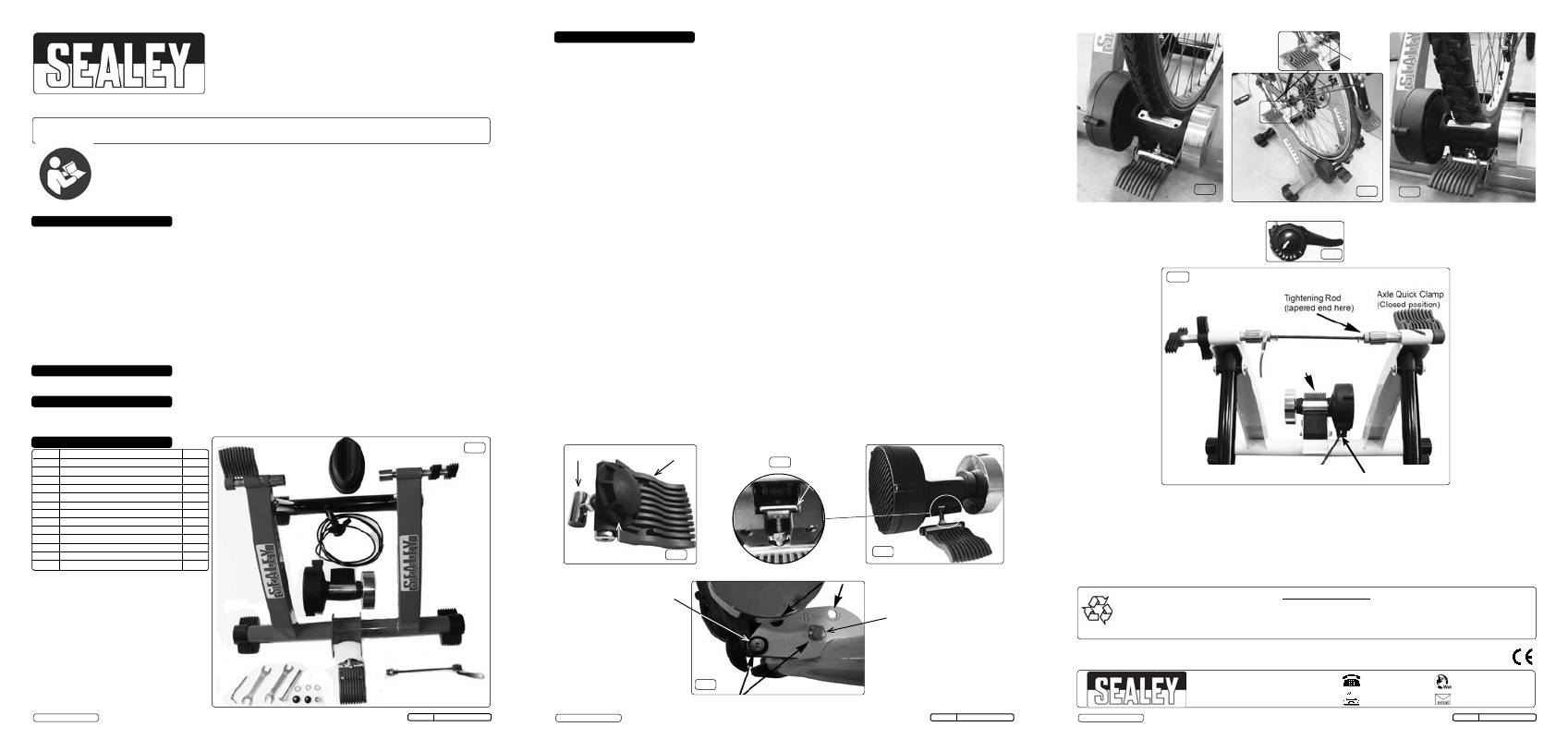
5.2. Fitting the cycle to the Pro Trainer. (quick release hollow axle type)
5.2.1. release the quick release lever on the back wheel of your cycle and replace the axle with the quick release tightening rod item 3, supplied
with the Pro Trainer (fig.10). Tighten it an appropriate amount. Ensure the tapered end of your cycle’s tightening rod engages with the
tapered holding cup on the axle quick clamp; in the closed position.
5.2.2
. Tighten the “T” screw an appropriate amount to support the cycle and rider, then lock with the locknut.
5.2.3. Thread the cable for the handlebar resistance controls around your cycle and mount the resistance control to the handlebars. Make sure it
is in easy reach of the handlebars, and make sure the cable is clear of the wheels and pedals.
5.2.4. Place the anti-slip levelling stand under the front tyre.
5.2.5. Adjust the flywheel position to engage the tyre periphery. This will require trial and error rotation of the knob in fig.2.
5.2.5 Gently but firmly push the wheel quick clamp on the rear of the flywheel mechanism down to engage it with the rear wheel, (fig.6 & 8).
5.3. Fitting the cycle to the Pro Trainer. (solid rear axle types)
5.3.1. The cycle axle hexagon nuts will register with the counter bored and conical bored adjustable cups of the Pro Trainer, see fig.7. Ensure the
axle quick clamp is in the closed position. The quick release rod (item 3) is not required.
5.3.2. Tighten the “T” screw an appropriate amount to support cycle and rider; then lock with the locknut.
5.3.3. Thread the cable for the handlebar resistance controls around yourcycle and mount the resistance control to the handlebars. Make sure it
is in easy reach of the handlebars, and make sure the cable is clear of the wheels and pedals.
5.3.4. Place the anti-slip levelling stand under the front tyre.
5.3.5. Gently but firmly push the wheel quick clamp on the rear of the flywheel mechanism down to engage it with the rear wheel, (fig.6 & 8).
5.4. Operation
5.4.1.
Use the cycle’s own gears to achieve your desired level of effort.
5.4.2.
The resistance controller difference from 1 to 7 (fig.9) is only slight and can only be measured in energy used over a sustained period of
exercise. Remain in the chosen gear and choose position 7 for least resistance from the flywheel to position 1 for maximum resistance.
5.5. Removal
5.5.1. Remove the resistance controller (fig.9) from the handlebars.
5.5.2. Open the axle quick clamp on the top of the trainer by pressing up firmly yet gently, then loosen the securing nut on the opposite side.
remove the anti-slip levelling stand.
5.5.3. The cycle can now be removed.
5. ASSEMBLY
5
NOTE: It is our policy to continually improve products and as such we reserve the right to alter data, specifications and component parts without prior notice.
IMPORTANT: No liability is accepted for incorrect use of this product.
WARRANTY: Guarantee is 12 months from purchase date, proof of which will be required for any claim.
01284 757500
01284 703534
Sole UK Distributor, Sealey Group,
Kempson Way, Suffolk Business Park
,
Bury St. Edmunds, Suffolk,
IP32 7Ar
www.sealey.co.uk
fig.3
fig.4
fig.5
fig.2
700C Wheel size fixing positions “A”.
26” Wheel size fixing positions “B”.
700C setup
26” setup
Solid axle setup
Axle nut
in cup
Cable
Wheel Quick Clamp
Locknut
“T”
Screw
Hollow axle setup (cycle wheel removed)
Environmental Protection
Recycle unwanted materials instead of disposing of them as waste. All tools, accessories and packaging should be sorted,
taken to a recycling centre and disposed of in a manner which is compatible with the environment.
When the product becomes completely unserviceable and requires disposal, drain off any fluids (if applicable)
into approved containers and dispose of the product and the fluids according to local regulations.
6.1 Storage
To store, carefully fold the Pro Trainer flat, and avoid storing other equipment on top of it. Keep all items together as in fig.10 indoors.
Wheel engage
adjustment knob
4
Cam
track
fig.6
fig.7
fig.8
fig.9
fig.10
resistance
controller
BC301 Issue: 2(I) - 16/12/14
© Jack Sealey Ltd
Original Language Version
BC301 Issue: 2(I) - 16/12/14
© Jack Sealey Ltd
Original Language Version
6,9,10
7,8
resistance
controller
Cable Adjustment