Installation – Livarno LSL 10 A1 User Manual
Page 8
LIVARNO LUX LSL 10 A1
6 - English
Installation
The installation must be performed only by an authorised
electrician!
The circuit must be disconnected during the installation!
Use suitable tools for the installation.
When drilling the holes, make sure that no cables or pipes in the
wall are damaged.
Only use a power cable [5] of type H05RN-F.
Remove the mounting bracket [3] from the LED spotlight [1].
Use the mounting bracket [3] as a template to mark the two outer holes.
Then drill two holes and attach the mounting bracket [3] using the
supplied plugs and screws.
Open the junction box [2] by loosening the four screws and removing the
cover.
Loosen the cable gland [4] and remove the rubber seal.
Put the nut of the cable gland [4] and then the rubber seal with the flat
side first on the power cable [5].
Run the power cable [5] through the cable gland [4].
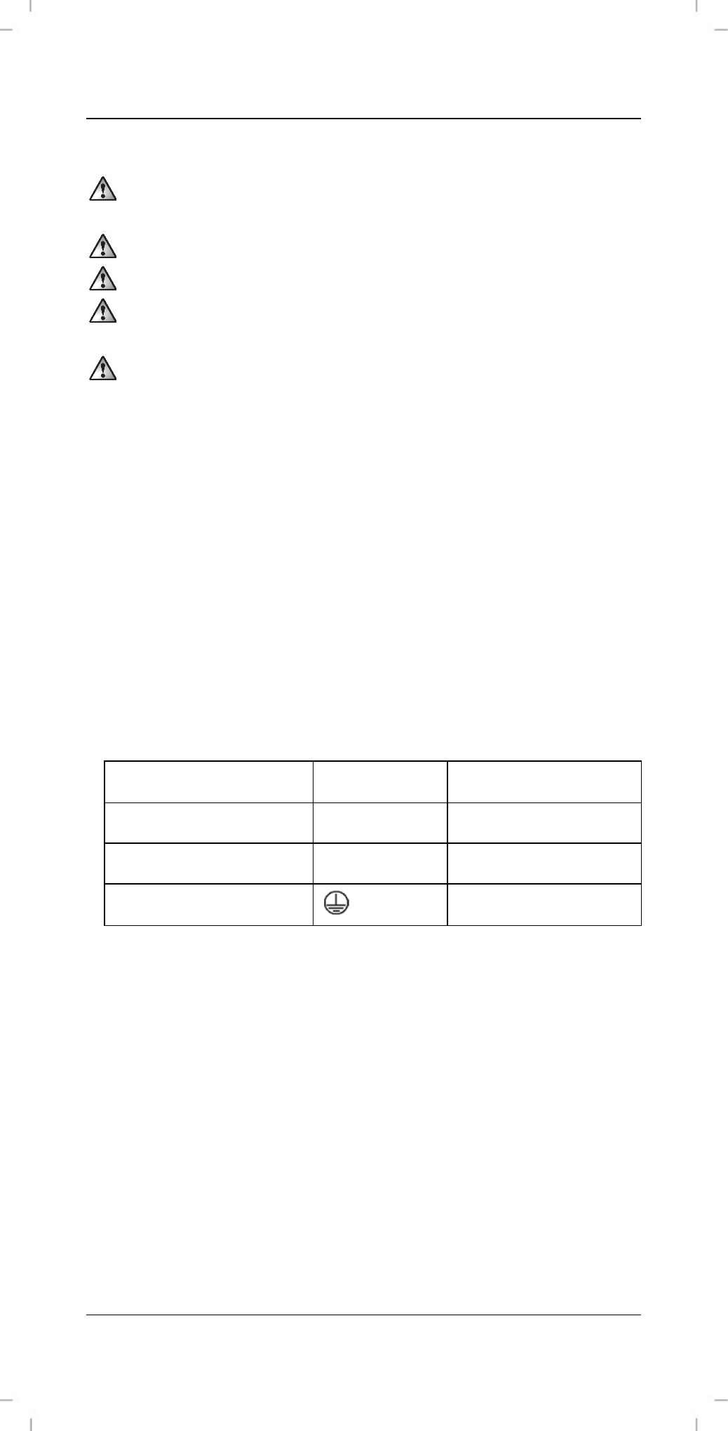
Connect the power cable [5] using the screw terminal [6]. Make sure that
the individual wires of the power cable [5] are connected correctly.
Wire
Symbol
Designation
Black or brown
L
Phase
Blue N
Neutral
Yellow/green
Earth conductor
Then screw the power cable [5] with the rubber seal tightly in the cable
gland [4].
Close the junction box [2] by screwing the cover again tightly with the
four screws that you previously removed. When closing the junction box
[2], ensure that the sealing ring lies in the groove. Otherwise, the IP
protection is not guaranteed.
Then attach the LED spotlight to the mounting bracket [3]. To do so, use
the previously removed screws and washers. Make sure that the spring
washers are located between the LED spotlight [1] and the mounting
bracket [3]. The other washers must be between the screw head and the
mounting bracket [3].