Preparation, Connecting devices – Silvercrest WIRELESS SOCKET SET User Manual
Page 10
10 GB/IE
Preparation
Remove the cover
11
above the
compartment of the DIP switch
10
.
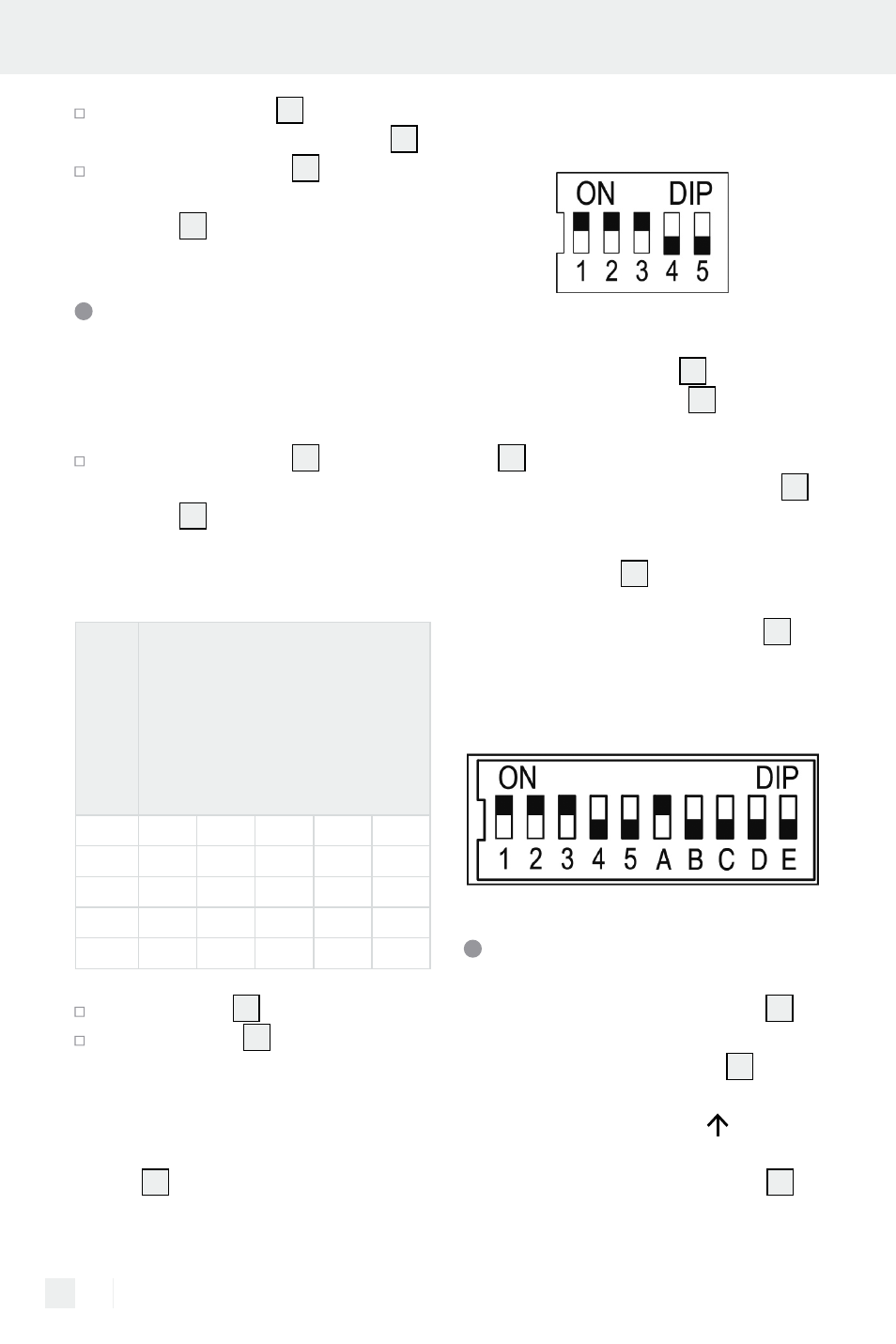
With the DIP switch
10
put in the
same system code as the remote
control
1
with the number 1 to 5.
Allocate the remote
controlled socket a
control button on the
remote control
With the DIP switch
10
put in a
control button, A to D, into remote
control
1
:
Note: E can not be selected with
the DIP switch.
Contr
ol butt
on
R
emo
te Contr
ol
DIP switch
remote controlled socket
A
B
C
D
E
A
ON OFF OFF OFF OFF
B
OFF
ON OFF OFF OFF
C
OFF OFF
ON OFF OFF
D
OFF OFF OFF
ON OFF
Put the cover
11
back on.
Put the screws
12
in the threads of
the screw holes and tighten them.
Example
Put the system code 123 into the remote
control
1
by pushing the DIP switch
up to „1“, „2“ and „3“ whist keeping
„4“ and „5“ in the down position:
View back side of the remote
control
Put the system code 123 in all of the re-
mote controlled sockets
7
. For the first
remote controlled socket
7
chose the
control button „A“ on the remote con-
trol
1
by pushing the DIP switch „A“
up for the remote controlled socket
7
whilst keeping the DIP switches B, C,
and D in the down position. This remote
controlled socket
7
can now be
switched on and off with the control
button „A“ on the remote control
1
.
View back side of the remote
controlled socket
Connecting devices
Plug the remote controlled socket
7
into an earthed household socket.
The remote controlled socket
7
can
only be plugged in the direction shown
on the device label (arrow must be
pointing up).
The range of the remote control‘s
1
radio signal reaches max. 40 m and is
dependent on the structural conditions.