Powerfix Aluminium Insect Protection Blind User Manual
Mn o, Alu-insektenschutz-türrollo, Aluminium insect protection blind
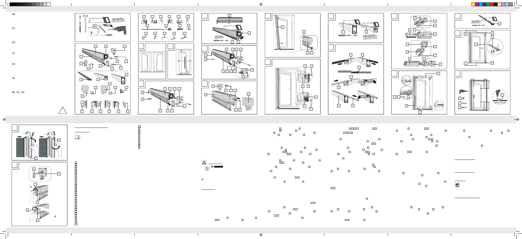
Detensioning the retractor spring if it has too much tension:
j
To do this, first release the locking thread again through a half-turn anticlockwise using
the crank
16
.
Attention: Do not let go of the crank
16
. Draw the locking thread
20
approx. 2 cm outwards using the crank and then grip the locking thread
20
between
your thumb and index finger.
Attention: Do not, under any circumstances, let go of
the locking thread
20
, otherwise the retractor spring will become completely detensioned.
Now turn the crank the desired number of turns clockwise to reduce the tension in the
retractor spring. From the factory preset tension, you can turn the crank a maximum num-
ber of 12 turns clockwise to detension the spring. After successfully reducing the tension,
you must now move the locking thread
20
carefully into the roller blind cassette and
then lock it by turning it through a half-turn anticlockwise (Fig. Q).
Attention: Do not
use too much force when relocking.
Note: If the locking thread slips out of your fingers, then you must retension the retractor
spring as described in the section “Tensioning the retractor spring”.
Q
Cleaning and care
J
Do not under any circumstances use corrosive or abrasive cleaning agents.
j
Clean the fibreglass fabric and frame with a lint-free, slightly damp cloth.
j
Use a mild cleaning agent where necessary.
Q
Installation video
For installation video visit www.feinheim.de.
Q
Disposal
The packaging is made entirely of recyclable materials, which you may dispose
of at local recycling facilities.
Contact your local refuse disposal authority for more details of how to dispose of your
worn-out product.
Q
Manufacturer / Service
FeinHeim GmbH
Bischof-Otto-Str. 60
D-94486 Osterhofen
Service hotline: +49-9932-4025 897
E-mail: [email protected]
Last Information Update: 02 / 2011
Ident no.: 022011-4
GB
GB
GB
GB
GB
GB
GB
Step 18
Remove the magnetic strip
2
and the guide channels
3
,
4
and drill the holes for the
dowels
18
using a 6 mm masonry drill bit. Clean out the drilled holes and insert the dowels
18
.
Step 19
Push the bottom guide channel
3
on to the roller blind cassette
1
and clamp the roller
blind cassette into the door reveal. Ensure that the wheel
12
runs on the guide channel.
Now insert the top guide channel
4
. Fix the guide channels
3
,
4
by means of the
clamping bolts
6
into the door reveal and put on the bolt covers
7 b
and
9 b
(see Fig. L).
Step 20
Pull off the protective foil from the self-adhesive strip of the magnetic strip
2
. Now reinstall
the magnetic strip following Steps A, B and C (see Fig. N).
Step 21
Screw the guide channels
3
,
4
and the magnetic strip
2
in place with the supplied
screws
19
(see Fig. O).
Q
Stopping the roller blind
j
If you decided in Step 9 to install the hook strips to stop the roller blind, you can now
set the roller blind in various positions.
Stopping the roller blind (Fig. P/1):
j
In this example, we are standing on the inside of the closed blind. Open the roller blind
and allow the roller blind to retract itself under hand control in the direction of the roller
blind cassette
1
. In the course of this movement, turn the handle profile
1e
towards
you. The roller blind hooks into the hook strip
11
.
Releasing the roller blind (Fig. P/2):
j
To release the stop, pull the roller blind slightly in the direction of the magnetic strip
2
.
When doing this, turn the handle profile
1e
towards the outside and allow the roller
blind to move smoothly into the roller blind cassette
1
.
Setting the retractor spring:
Note: Read through this step carefully and refer closely to Fig. Q.
Tensioning the retractor spring:
The insect screen door roller blind is optimally preset in the factory for average door sizes. If
the pretension is too low for your door, you can increase the tension of the retractor spring.
To do this, proceed as follows:
j
Release the locking thread
20
through a half-turn anticlockwise using the crank
16
.
Attention: Do not let go of the crank
16
. The locking thread
20
can be seen to move
out. Now crank the required number of turns in the same direction. After successfully
tensioning the spring, you must turn the locking thread
20
carefully through a half-turn
clockwise to lock it again.
Attention: Do not use too much force when relocking.
Note: You can add 12 turns anticlockwise to the preset 18 turns to bring the retractor
spring to its maximum tension (30 turns) (see Fig. Q).
Step 10
Use the appropriate clamping feet
7
,
8
,
9
,
10
for the guide channels
3
,
4
, depending
on how the roller blind is installed in the door reveal (variant A or B, see Fig. A). The rounded
part of the clamping feet
7
,
8
,
9
,
10
must coincide with the rounded part of the roller
blind cassette, and point outwards. To simplify the description of the remaining step, we will
refer to the figures and installation variant A (see Fig. A) in these installation instructions.
Fit a clamping bolt
6
into the clamping end internal part of the top guide channel
7 a
and
into the clamping end internal part of the bottom guide channel
8 a
as shown in Fig. K. Fit
the clamping end parts together and then on to the two guide channels
3
,
4
(see Fig. K).
Step 11
Push the bottom guide channel
3
on to the roller blind cassette
1
and clamp the roller
blind cassette into the door reveal. Ensure that the wheel
12
runs on the guide channel
3
.
Now insert the top guide channel
4
. Fix the guide channels
3
,
4
by means of the
clamping bolts
6
into the door reveal and put on the bolt covers
7 b
and
9 b
(see Fig. L).
Step 12
Saw the magnetic strip
2
to length H minus 50 mm using a hacksaw and deburr the sawn
edges using a file (see Fig. M).
Step 13
Pull off the protective foil from the self-adhesive strip of the magnetic strip
2
. Next insert the
magnetic strip into the recess provided for this purpose in the clamping end
9
of the bottom
guide channel
3
(Step A, Fig. N). Insert the magnetic strip
2
into the recess in the clamping
end
7
of the top guide channel
4
(Step B, Fig. N). Now press the magnetic strip
2
firmly
on to the door reveal (Step C, Fig. N).
Q
Alternative installation with screws
j
Carry out Steps 1 to 8 described in the section “Installation by clamping”.
Step 14
Measure approx. 12 cm in from the right and left ends of the top and bottom guide chan-
nels
3
,
4
and drill a hole using a 3.5 mm drill bit at each of the four locations. When
drilling the holes, use the drilling aid to ensure that you drill exactly in the middle of the pro-
file (see Fig. O).
Carry out Steps 9 to 12 described in the section “Installation by clamping”.
Step 15
Measure approx. 60 cm in from the ends of the magnetic strip
2
and drill a hole using a
3.5 mm drill bit at each of the two locations.
Step 16
Leave the protective foil on the self-adhesive strip of the magnetic strip. Next insert the mag-
netic strip into the recess provided for this purpose in the clamping end
9
of the bottom
guide channel
3
(Step A). Then insert the magnetic strip
2
into the recess in the clamping
end
7
of the top guide channel
4
(Step B). Now position the magnetic strip
2
so that it
bears against the door reveal (Step C) (see Fig. N).
Step 17
Now mark the positions on the wall of the holes to be drilled in the next step through the
holes in the guide channels
3
,
4
and the magnetic strip
2
.
Step 3
Bring the handle profile
1e
and the roller blind cassette
1
together as shown in Fig. D and
align the handle profile
1e
and the magnetic strip
1f
so that they end flush with the roller
blind cassette
1
. Hold them all firmly together and saw the roller blind cassette
1
, fibre-
glass fabric blind roll
1a
, handle profile
1e
and magnetic strip
1f
at the same time to a
length of H minus 15 mm using a hacksaw. If necessary, use a mitre box for this. Remove
any burrs from the sawn edges using a file.
Attention: The blind has a retractor spring,
which means that the roller blind cassette can be sawn no shorter than 70 cm in length (see
Fig. D).
Step 4
Fix the cassette end cover
1b
back on to the roller blind cassette
1
(see Fig. E). Ensure that
the projecting tab of the adapter
1c
engages into the slot of the fibreglass blind roll
1a
.
Then place the two end caps
1g
,
1i
on the handle profile
1e
. Ensure that the magnetic
strip
1f
is pushed into the end caps
1g
,
1i
. Now insert a clamping bolt
6
and nut into
each of the two cassette end covers (see Fig. E).
Step 5
Insert the friction springs
13
and the friction pins
14
into the recess of the cassette end cover
1b
and place the end caps
5 a
,
5 c
on to the roller blind cassette
1
(see Fig. F).
Step 6
Guide the wheel
12
from the side into the end cap of the handle profile
1e
, which will be at
the bottom once the roller blind cassette
1
is finally installed. Then clamp the roller blind
cassette
1
into the door reveal (Fig. G).
Step 7
Clamp the roller blind cassette firmly into the door reveal at the top and bottom with the
clamping bolts
6
and put on the two bolt covers
5 b
,
5 d
(see Fig. H).
Step 8
Saw the bottom guide channel
3
and the top guide channel
4
to the length B minus
63 mm and deburr the cut edges using a file (see Fig. I).
Q
Installation with/without stop
j
You have the choice of installing the roller blind with or without a stop (the stop allows
the blind to be fixed in different positions).
Installation with stop: Continue with Step 9 and Fig. I
Installation without stop: Continue with Step 10 and Fig. J
Step 9
Pull the brush seals out of the grooves in the top and bottom guide channels
3
,
4
, which
will be on the outside of the blind once the roller blind cassette has been installed in the
door reveal. Fit the hook strips
11
together as shown in Fig. J and push them into the open
grooves in the top and bottom guide channels
3
,
4
.
Attention: Ensure that the hook
strips
11
are installed so that the hooks point away from the roller blind cassette
1
(see de-
tails I and II Fig. L). Push the hook strips
11
through until they are flush with one end of the
guide channels
3
,
4
and cut the surplus at the projecting end to length using a carpet
knife or scissors (see Fig. J).
Attention: Cut the hook strips
11
to length at the same end
in each case, otherwise the roller blind may not work properly in the future.
1 Clamping end internal part for bottom guide channel (left)
1 Screw cover for clamping end for bottom guide channel (left)
1 Clamping end for bottom guide channel (right)
1 Clamping end internal part for bottom guide channel (right)
1 Screw cover for clamping end for bottom guide channel (right)
10 Hook strips
1 Wheel
2 Friction springs
2 Friction pins
1 Drilling aid
1 Crank
1 Allen key
6 Dowels
6 Countersunk head screws
1 Assembly instructions
Safety advice
J
WARNINg!
RISK OF FATAL INJURY AND RISK OF ACCI-
DENTS FOR INFANTS AND CHILDREN! Never leave children unattend-
ed with the packaging material or the product. There is a risk of suffocation
from the packaging materials and a risk of fatal injury by strangulation. Children often
underestimate dangers. Always keep children away from the product. The product is not
a toy.
CAUTION! RISK OF INJURY! Ensure that all parts are undamaged and have
been assembled appropriately. Risk of injury exists if assembled incorrectly. Damaged
parts can effect safety and function.
Q
Installation
j
Check before installation that your door reveal is suitable for this product and does not
exceed the maximum allowable dimensions. The depth of the reveal must not be less
than 5.5 cm. The insect screen door roller blind can be fixed into the reveal by clamping
or screwing (recommended). If necessary, have a second person help you with the in-
stallation.
Q
Installation by clamping
You can install the insect screen door roller blind in your reveal as left-opening (variant A) or
as right-opening (variant B) to suit your requirements (see Fig. A).
Step 1
Measure the height (H) and width (B) of your door reveal (see Fig. B).
Step 2
Unscrew the cassette end cover (cut end)
1b
as shown in Fig. C and take off the adapter
1c
.
Remove the end caps
1g
,
1i
from both ends of the handle profile
1e
(see Fig. C).
Note: Ensure that you do not lose the removed parts.
10 b
Screw cover for clamping end for bottom guide channel (right)
11
Hook strip
12
Wheel
13
Friction spring
14
Friction pin
15
Drilling aid
16
Crank
17
Allen key
18
Dowel
19
Countersunk head screw
20
Locking thread (installed in cassette end cover, see Fig. Q)
Q
Technical data
Max. dimensions of the door reveal: 125 x 220 cm (W x H)
Q
Included in delivery
Note: When opening the packaging, please make sure not to accidentally throw away
assembly materials. Please check immediately on unpacking that the delivery is complete
and that the product and all parts are in perfect condition. Do not under any circumstances
assemble the product if the delivery is incomplete.
1 Roller blind cassette
1 Fibreglass fabric blind roll
1 Cassette end cover (cut end)
1 Adapter
2 Screws for cassette end cover (cut end)
1 Handle profile
1 Magnetic strip
1 End cap (handle profile, right)
2 Screws for end cap (handle profile, right)
1 End cap (handle profile, left)
2 Screws for end cap (handle profile, left)
1 Magnetic strip
1 Bottom guide channel
1 Top guide channel
1 Cassette end cap left
1 Screw cover for end cap (left)
1 Cassette end cap (right)
1 Screw cover for end cap (right)
4 Clamping bolt with nut
1 Clamping end for top guide channel (left)
1 Clamping end internal part for top guide channel (left)
1 Screw cover for clamping end for top guide channel (left)
1 Clamping end for top guide channel (right)
1 Clamping end internal part for top guide channel (right)
1 Screw cover for clamping end for top guide channel (right)
1 Clamping end for bottom guide channel (left)
Aluminium Insect Protection Blind
Q
Introduction
Please familiarise yourself with the product prior to assembly. Carefully read the
following assembly instructions and safety tips. Only use the unit as described and
for the specified applications. Store these instructions in a safe place. If passing
this product on to a third party also include all documents.
Q
Intended Use
This article is designed to provide protection against insects such as flies and is intended for
indoor use only. Any use other than previously mentioned or any product modification is pro-
hibited and can lead to injuries and / or product damage. The manufacturer is not liable for
any damages caused by any use other than for the intended purpose. The product is not
intended for commercial use.
Q
Description of parts and features
1
Roller blind cassette
1a
Fibreglass fabric blind roll
1b
Cassette end cover (cut end)
1c
Adapter
1d
Screws for cassette end cover (cut end)
1e
Handle profile
1f
Magnetic strip
1g
End cap (handle profile, right)
1h
Screws for end cap (handle profile, right)
1i
End cap (handle profile, left)
1j
Screws for end cap (handle profile, left)
2
Magnetic strip
3
Bottom guide channel
4
Top guide channel
5 a
Cassette end cap (left)
5 b
Bolt cover for end cap (left)
5 c
Cassette end cap (right)
5 d
Bolt cover for end cap (right)
6
Clamping bolt with nut
7
Clamping end for top guide channel (left)
7 a
Clamping end internal part for top guide channel (left)
7 b
Screw cover for clamping end for top guide channel (left)
8
Clamping end for top guide channel (right)
8 a
Clamping end internal part for top guide channel (right)
8 b
Screw cover for clamping end for top guide channel (right)
9
Clamping end for bottom guide channel (left)
9 a
Clamping end internal part for bottom guide channel (left)
9 b
Screw cover for clamping end for bottom guide channel (left)
10
Clamping end for bottom guide channel (right)
10 a
Clamping end internal part for bottom guide channel (right)
ALU-INSEKTENSCHUTz-TüRROLLO
Montage- und Sicherheitshinweise
ALUMINIUM INSECT PROTECTION
BLIND
Assembly and safety advice
ALUMINIOWA ROLETA CHRONIąCA
PRzED OWADAMI
Wskazówki dotyczące montażu oraz bezpieczeństwa
ALU AJTó SzúNYOgHáLó
Használati- és biztonsági utasítások
ALUMINIJASTI ROLO KOMARNIK
Navodila za montažo in varnost
HLINíKOvá, ROLOvACí OCHRANA
PROTI HMYzU
Pokyny k montáži a bezpečnostní pokyny
HLINíKOvá, PROTIHMYzOvá ROLETA
NA DvERE
Pokyny pre montáž a bezpečnosť
4
1
1 x
9
1 x
11
10 x
15
1 x
16
1 x
17
1 x
18
1 x
19
1 x
13
2 x
14
2 x
12
1 x
9 a
1 x
10
1 x
9 b
1 x
5 b
1 x
7
1 x
7 a
1 x
7 b
1 x
8
1 x
8 a
1 x
8 b
1 x
5 c
1 x
5 d
1 x
6
4 x
1e
1 x
1i
1 x
2
1 x
5 a
1 x
3
1 x
1j
2 x
1f
1 x
1b
1 x
1c
1 x
1g
1 x
1h
2 x
1d
1 x
4
1 x
D
E
F
C
G
H
1a
1
1
1
B
A
H
B
1a
1 x
ø 3,5 mm
1 x
10 a
1 x
10 b
Variant A
(Roller blind left)/
Variante A
(Rollo links)
Variant B
(Roller blind right)/
Variante B
(Rollo rechts)
1h
1b
1c
1i
1j
1a
1
1g
1e
1f
min. 70 cm
H - 15 mm
1f
1e
1b
5a
1c
1i
1j
1
1
5 c
1a
17
1a
1g 1h
1e
12
1g
6
5 b
13
13 14
16
5 d
6
17
14
1f
6
1
I
J
4
3
3
4
11
3
11
4
11
B - 63 mm
K
L
6
7
7
6
6
9
1
9 b
4
9
9 a
7a
7a
4
3
3
17
9 a
7 b
I
II
III
M
N
O
2
H - 50 mm
7
9
15
18
19
2
4
3
2
15
B
C
A
ø 3,5 mm
approx./
ca. 12 cm
approx./
ca. 12 cm
approx./
ca. 60 cm
approx./
ca. 60 cm
P
Q
16
20
1e
1e
16
16
20
20
1
2
max. 12
max. 12
You need · Potrzebujecie · Szüksége van · Potrebujete · Potřebujete
Budete potrebovať · Sie benötigen:
61066_Insektenschutz-Türrollo_Content_LB4.indd 1
28.02.11 15:10