Powerfix ALUMINIUM INSECT SCREEN BLIND User Manual
Aluminium insect screen blind, Alu szúnyoghálós ablakroló, Ochranná roleta proti hmyzu v hliníkovém rámu
GB
GB
GB
GB
GB
Note: If your window has no outside ledge, to obtain optimal sealing, prior to mounting
the end parts of the handle bars, pull out
6
the brush seal
10a
at the bottom of the handle
bar
1b
and push it into the lateral nut in the handle bar, designed for this purpose
1b
on the
side facing the window (Detailed image fig. R).
Step 9
Subtract 2 mm from the measured height (H) and transfer this measurement to the guide
channels
2
.
Step 10
Using a iron saw, cut the guide channels
2
to the correct length and polish the sawn edge
with a file (see fig. H).
Follow steps 11 and 12 in the chapter “Installation in the window reveal“.
Step 13
Mount the cover
3b
and a roller blind cassette holder
13
with a screw
14
to the roller blind
cassette
1
. Mount the second roller screen cassette holder
13
likewise using a screw
14
to
the other side of the roller screen cassette
1
(see fig. R).
Step 14
Mount the guide channel holder
12
below to the locking parts
7
(see fig. S).
Step 15
Screw the roller screen cassette
1
using the screws
14b
through the roller screen cassette
13
frontally to the wall, in front of the window reveal. Mount the roller screen cassette
1
in
such a way that the handle bar
1b
is visible in the window reveal and you are able to grasp
into the handle recesses
4
to operate the roller screen.
Attention: Use a spirit level for
the installation (see fig. T).
Step 16
Insert the guide channels
2
into the corresponding latches of the cover
3a
3b
, push them
up as far as they will go to ensure that the guide channels
2
will be seated at the point of
impact between the covers
3a
3b
of the roller screen cassette
1
and mount firmly to the
wall using screws
14b
though the guide channel holders
12
. Ensure that the screw hooks
7a
in the locking parts
7
are facing the window (see fig. T).
Attention: Use a spirit level for
the installation.
Follow steps 17 and 18 in the chapter “Installation in the window reveal“.
Note: If the wall texture prohibits optimum locking of the guide channels
2
with the sur-
face of the wall, the guide channels can each be mounted
2
using a screw
14
to the wall.
To achieve this purpose, define a drilling point approx. in the middle of the guide channels
2
and drill a hole through the profile panels with a 4 mm drill (see fig. T). Remove the guide
channels
2
, insert the dowel plugs and remount the guide channels
2
. Now drill holes
that are visible in the outer frames of the profile using an 8 mm drill (size of the screw head).
Mount the guide channels
2
using the screws
14
to the wall through the holes. Seal the
8 mm drill holes with the caps
15
(see fig. T).
Installation outside the window reveal in windows
with window ledges
If the window is equipped with a window ledge, the guide channel holders cannot be
mounted
12
. Place the guide channels
2
on the window ledge. Define a drilling point A
Step 16
Stick the double-sided adhesive tape
11
approx. 2 cm from the bottom edge, to which the
locking parts
7
are attached, to the guide channels
2
. Remove the protective foil (see
detail 1, fig. N). Insert the guide channels
2
left and right into the respective latch of the
cover
3a
3b
and align by pushing them up into the latches of the cover
3a
3b
in the win-
dow reveal (fig. N).
Attention: The screw hooks
7a
of the locking parts
7
must be facing
towards the window (see detailed image 2, fig. N). Ensure that the guide channels
2
are
correctly aligned, this means that the the back of the roller blind
1
and the rear sides of the
guide channels
2
form one surface and therefore exhibit a uniform clearance to the outer
edge of the wall. You can now press the guide channels
2
firmly to the wall reveal to
adhere them into place (see fig. N).
Alternative screw assembly: Alternatively, the
guide channels
2
can also be screw mounted by applying to each guide channel
2
two
screws
14
at an equal distance to mount the guide channels
2
to the window reveal. Pro-
cure dowel plugs matching the screws included in the delivery according to the structure of
the wall. Using a 4 mm drill, drill a hole through the rear profile of the guide channels posi-
tioned in the reveal
2
(Detailed image, fig. O), in this way you will obtain the corresponding
marking on the window reveal. Now remove the guide channels
2
from the reveal, insert
the matching dowel plugs into the reveal at the markings and screw the guide channels
2
following renewed insertion into the latches of the cover
3a
3b
with the screws
14
through
the drilled holes on the reveal (see fig. O).
Step 17
Pull down the roller screen and hook the handle bar
1b
into the screw-in hooks
7a
of the
locking parts
7
. To accomplish this, pull down the handle bar
1b
, tilt it towards your body
and allow the handle bar to snap into place
1b
into the screw-in hooks
7a
(see fig. Q1).
Note: If the roller screen does not snap into place immediately, keep the handle bar
pressed down
1b
while you continue to screw down the screw-in hooks
7a
in the direction
of the handle bar
1b
(see fig. P).
Attention: In any case, hold the handle bar
1b
firmly
until correct hooking in has been achieved to prevent the roller screen from springing back.
In this way you can now correct potential level differences between the bush and the wall
by turning the screw-in hooks downwards while the roller blind is closed. Do not screw too
far down to avoid bending the bush seal in the handle bar
1b
which would impair the sealing.
Step 18
To open the roller blind, press down the handle bar
1b
and then tilt it outwards away from
your body to unhook it. Allow the fibre glass fabric to slowly roll back into the roller blind
cassette (see fig. Q2).
Alternative option of installation on the wall, in front
of the window reveal
If you have no possibility of installing the roller blind in your window reveal, you can mount
it on the wall, in front of the reveal.
Step 1
Measure the height (H) and width (W) of your window reveal (see fig. A).
Step 2
Add 72 mm to the measured width (W) and transfer the resulting dimensions to the measuring
tape of the roller blind cassette
1
.
Follow steps 3 to 8 in the chapter “Installation in the window reveal“.
Step 2
Remove the self-adhesive bush seal
10
from the inside of the handle bar
1b
(see fig. B).
Step 3
Transfer the dimensions of the measured width (B) to the measuring tape of the roller blind
cassette
1
.
Note: The cassette
1
can be shortened to maximum 70 cm, regardless of the
printed measuring tape length. Draw out the fibre glass fabric
1a
a little and wrap it round
the roller blind cassette
1
, ensuring that the fabric
1a
cannot return to the cassette
1
. If
necessary, have a second person help you with the installation. Ensure that the roller blind
cassette
1
, the fibre glass fabric
1a
and the handle bar
1b
form one surface (see fig. C).
Step 4
Now saw through the roller blind cassette
1
, the fibre glass fabric
1a
and the handle bar
1b
with an iron saw (see fig. C).
Note: Use a mitre box for this purpose.
Step 5
Polish the interface with a file and remove the aluminium filings with a paint brush.
Step 6
Fix the cover
3a
to the interface of the roller blind cassette
1
with a screw
14a
(see fig. D).
Step 7
Slide one of the handle recesses first
4
, then the cord
5
and finally the second handle
recess
4
into the slot provided for that purpose
1b
(see fig. E).
Step 8
Place the end caps
6
left and right onto the handle bar
1b
(see fig. F).
Step 9
Stick the self-adhesive bush seal
10
centred to the ceiling side of the roller screen cassette
1
(see fig. G) and cut off the protruding end.
Note: This step can be omitted in the case of
installation outside the reveal.
Step 10
Subtract 46 mm from the measured height (H) and transfer this measurement to the two
guide channels
2
. Using a iron saw, cut the guide channels
2
to the correct length (see
fig.H).
Note: Use a mitre box for this purpose. Then remove any burrs from the sawn edges
using a file.
Step 11
Using pliers, clamp the brush seal carrier at the lower end of the guide channels
2
together
with the integrated bush seal. In this way you will prevent the bush from sliding out during
application (see fig. I).
Step 12
Screw one retaining hook
7a
into each of the locking parts
7
and attach the locking parts
7
together with the retaining hooks
7a
to the bottom of the two guide channels
2
(see fig. J).
Step 13
Attach the two bow springs
8
to the sealing cover
3a
(see fig. K).
Note: This step can be
omitted in the case of installation outside the reveal.
Step 14
Attach the two bow springs
8
to the sealing cover
3b
and position this together with the
spiral spring
9
on the roller screen cassette
1
(see fig. L). Keep this firmly pressed to the
cassette
1
.
Step 15
Keeping the cover
3b
firmly pressed to the roller screen cassette
1
, clamp the cassette
1
into the wall reveal (see fig. M).
Attention: Ensure that the roller blind cassette
1
is cor-
rectly mounted, this means a uniform clearance to the outer edge of the wall throughout the
entire width.
1 Roller blind cassette
1 Fibreglass fabric
1 Handle bar
2 Guide channels
2 Cover
2 Handle recesses
1 Pull cord
2 Handle bar end parts
2 Locking parts
2 Screw hooks
4 Bow springs
1 Spiral spring
1 Brush seal, self-adhesive
1 Brush seal handle bar
2 Double-sided adhesive tapes
2 Guide channel holders
2 Roller blind cassette holders
9 Screws
4 Caps
1 Installation instructions
Safety advice
RISK OF FATAL INJURY AND RISK OF ACCIDENT
FOR INFANTS AND CHILDREN! Never leave children unattended with
the packaging material or the product. There is a risk of suffocation from the
packaging materials and a risk of fatal injury by strangulation. Children often underestimate
dangers. Please keep children away from the device at all times. The product is not a toy.
DANGER TO LIFE! Do not lean too far out of the window when you
are installing, removing or cleaning the product.
CAUTION! RISK OF INJURY! Please ensure that no parts are damaged and that
all parts are correctly assembled. Risk of injury exists if assembled incorrectly. Damaged
parts can effect safety and function.
Installation in the window reveal
Check before installation that your window reveal is suitable for this product and does
not exceed the maximum permissible dimensions. The depth of the reveal must not be
less than 5 cm. If necessary, have a second person help you with the installation.
Note: If your window opens outwardly, you can also mount the roller blind to the inside of
the window or to the reveal.
Step 1
Measure the height (H) and width (B) of your window reveal (see Fig. A).
Attention: Take into account any differences in length between the left and right windows,
as the window reveal is not always equal, especially in older buildings.
Aluminium Insect Screen Blind
Introduction
Familiarise yourself with the product prior to assembly. Carefully read the follow-
ing assembly instructions and safety tips. Only use the product as described and
for the specified applications. Keep the instructions in a safe place, you might
need them later. If passing this product on to a third party also include all documents.
Proper use
This article is designed to provide protection against insects such as flies and is intended for
indoor use only. Any use other than previously mentioned or any product modification is
prohibited and can lead to injuries and / or product damage. The manufacturer is not liable
for any damages caused by any use other than for the intended purpose. The product is not
intended for commercial use.
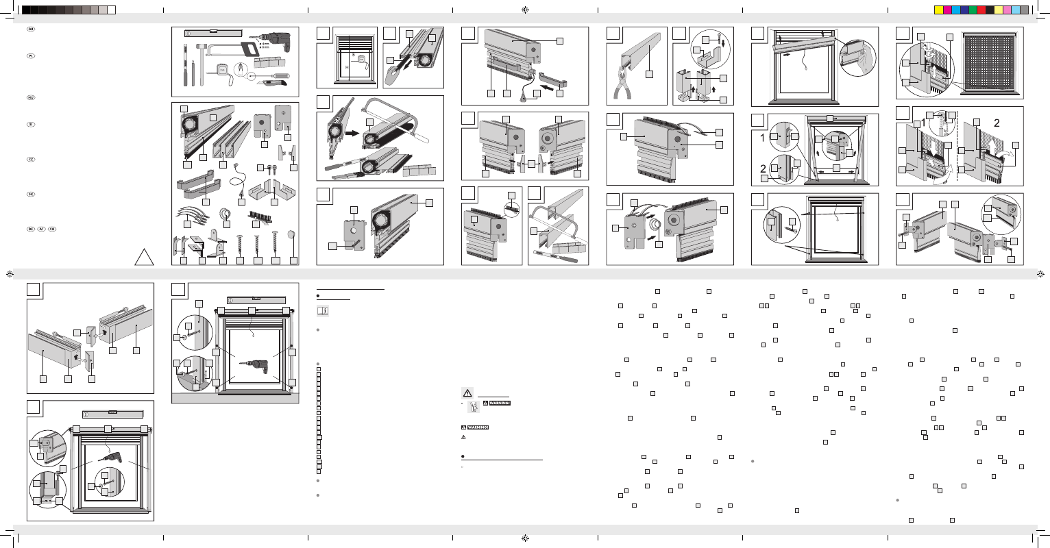
Description of parts and features
1
Roller blind cassette
1a
Fibre glass fabric
1b
Handle bar
2
Guide channel
3a
Cover
3b
Cover
4
Handle recess
5
Pull cord
6
Handle bar end part
7
End part
7a
Screw-in hook
8
Bow spring
9
Spiral spring
10
Brush seal, self-adhesive
10a
Brush seal handle bar
11
Double-sided adhesive tape
12
Guide channel holder
13
Roller blind cassette holder
14
Round head screw
14a
Flat head screw
14b
Round head screw long
15
Cover caps
Technical data
Max. dimensions of window reveal: 130 x 160 mm (W x H)
Included items
Note: When opening the packaging, please make sure not to accidentally throw away
assembly materials. Please check immediately on unpacking that the delivery is complete
and that the product and all parts are in perfect condition. Do not under any circumstances
assemble the product if the delivery is incomplete.
C
1
D
14a
1
3a
F
1b
1b
1
1
6
A
B
10
1
1b
G
H
1
10
2
K
8
1
3a
I
J
2
7a
2
7
7
L
3b
1
8
9
M
E
4
4
1b
1
5
P
2
7
1b
7a
Q
2
7a
2
7
7
1b
1b
1b
7a
7a
N
11
2
2
3a
3b
1
2
7
7a
2
O
14
2
R
1
13
10a
13
1
1
14
3b
14
S
12
2
7
7
12
2
T
14b
3b
3a
1
14
15
2
2
12
7a
13
14
You need · Potrzebujecie · Szüksége van
Potrebujete · Potřebujete · Budete potrebovať · Sie benötigen:
U
3
3
1
7
B
B
A
A
15
2
14
2
15
14
ALUmINIUm INSECT SCREEN BLIND
Assembly and safety advice
ALU SzúNYOGHáLóS ABLAKROLó
Használati- és biztonsági utasítások
OCHRANNá ROLETA PROTI HmYzU v
HLINíKOvém RámU
Pokyny k montáži a bezpečnostní pokyny
ALU-INSEKTENSCHUTz-FENSTERROLLO
Montage- und Sicherheitshinweise
ROLETA ALUmINIOwA CHRONIąCA
PRzED OwADAmI
Wskazówki dotyczące montażu oraz
bezpieczeństwa
ALUmINIJASTI OKENSKI ROLO zA
zAščITO PRED mRčESOm
Navodila za montažo in varnost
HLINíKOvá, PROTIHmYzOvá
OKENNá ROLETA
Pokyny pre montáž a bezpečnosť
4
1a
1b
3a
11
12
13
14
14a
14b
15
3b
1
1 x
1 x
2
2 x
1 x
7
2 x
4
2 x
5
1 x
2 x
2 x
2 x
6 x
1 x
2 x
4 x
9
1 x
10
1 x
8
4 x
1 x
6
2 x
7a
2 x
10a
1 x
1 x