Instruction on dip switch setting, 3 camera address selector, 4 system switch – Marshall Electronics CV620 User Manual
Page 2: 1 output switch 4.2 ir select
Marshall Electronics www.LCDracks.com
3. Lock the metal plate B on ceiling mounted hanger
※Caution:
* Please use the hanger that has obtained UL security approval.
* Please reserve the hole for the connecting wires of the camera.
4. Combine the metal plate A and the metal plate B
Push the metal plate A up to the ceiling and then to the right to latch the metal
plate B.
Fix with 3 M3 screws.
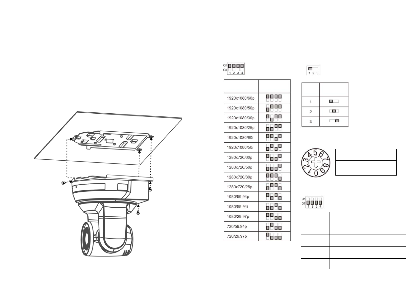
4. Instruction on DIP SWITCH Setting
ID Setting
4.3 Camera Address Selector
Setting
Function
Descriptions
0~7
ID 0~7
8~9
Reserved
4.4 System Switch
Setting
Function Descriptions
DIP 1
RS-232C/RS-422 selector
OFF: RS-232C / ON: RS-422
DIP 2
Infrared signal output switch
OFF: Off / ON: On
DIP 3
Communication baud rate selector
OFF: 9600 / ON: 38400
DIP 4
Reserved
4.1 OUTPUT SWITCH
4.2 IR SELECT
Output Mode
Setting