MEDC XB12 User Manual
Page 4
All cable glands should be of an equivalent NEMA/IP rating to that of the beacon and integrated with the unit such that
this rating is maintained.
The internal earth terminal, where fitted, must be used for the equipment grounding.
Once termination is complete, carefully replace the cover assembly back onto the base, avoiding damage to the mating
surfaces. Replace the 6 off M8 screws (6.0mm A/F hexagon key) into the holes in the cover assembly and tighten evenly.
Ensure the O-ring is seated correctly on the cover during re-assembly. Ensure the required maximum gap of 0.2mm is
maintained between the cover and the base once assembled.
3.0 OPERATION
The operating voltage of the unit is stated on the unit label. The unit can be powered directly or initiated via a telephone
ringing signal if requested when ordered.
4.0 MAINTENANCE
During the working life of the unit, it should require little or no maintenance. GRP will resist attack by most acids, alkalis
and chemicals and is as resistant to concentrated acids and alkalis as most metal products.
However, if abnormal or unusual environmental conditions occur due to plant damage or accident etc., then visual inspec-
tion is recommended.
If the unit requires cleaning, then only clean exterior with a damp cloth to avoid electro-static charge build up.
Replacement of the xenon tube (see below) can be carried out by competent site personnel. Other repairs should be
undertaken by returning the unit to MEDC or by an authorised repairer of Ex equipment.
If a unit fault should occur, then the unit can be repaired by MEDC. All parts of the unit are replaceable.
If you acquired a significant quantity of units, then it is recommended that spares are also made available. Please discuss
your requirements with the Technical Sales Engineers at MEDC.
Removing / replacing xenon tube
CAUTION: Before removing the cover assembly, ensure that the power to the unit is isolated.
Note: these units each contain two separate xenon tubes which should both be replaced at the same time.
Unscrew and remove the 6 off M8 (6.0mm A/F hexagon key). Keep in a safe, accessible location as they are non-
captive
Twist the cover assembly gently clockwise and anti-clockwise, whilst pulling it away from the base. Remove to gain access
to the interior.
Unscrew and remove the three M4 nuts holding the circuit board to the cover pillars. Keep in a safe accessible location.
Lift the electronics assembly away from the support pillars, thus exposing the xenon tube. Remove the old tube by unscrew-
ing the terminal block fixings. The replacement tube can now be fitted (see xenon tube installation sheet, which is supplied
with the replacement tubes)
Replace the electronics assembly onto the support pillars and secure using the three off M4 nuts. Ensure the retaining strap
is fitted to one of the electronics assembly mounting points during re-assembly.
©
02/11
12/11
© Cooper MEDC 2011
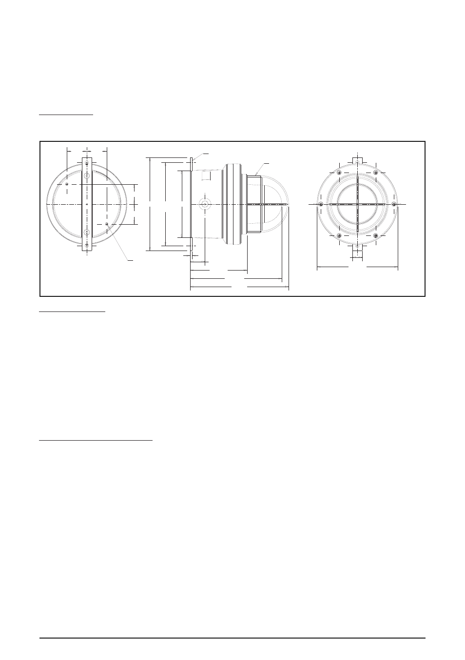
60±1
60±1
FIXING HOLES ø11.5±1
2 POSITIONS
OPTIONAL GUARD
ENTRY
‘R’
30±1
ø242±2
45±1
172.5±2
275.5±2
307±3
6±1
M8 X 11±1 DEEP
DIRECT MOUNTING
HOLES
2 POSITIONS
60±1
60±1
280±2 250±1
CRS
ø202±2
ENTRY
‘L’