Precision Digital PD650 User Manual
Page 73
Model PD650 Large Display Process Meter
Instruction Manual
73
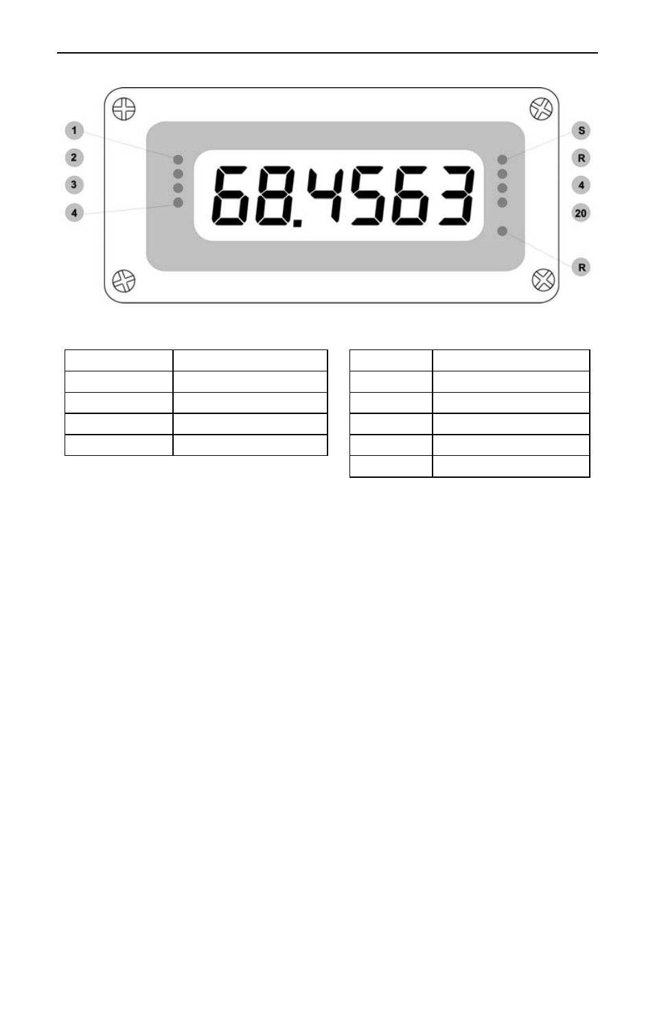
Front Panel LEDs
Figure 25. Front Panel LED Indicator Locations
The LEDs on the front panel provide status for the following:
LED Status
LED
Status
1
Alarm 1
S
Set point indicator
2
Alarm 2
R
Reset point indicator
3
Alarm 3
4
4 mA indicator
4
Alarm 4
20
20 mA indicator
R
Rate
indicator
The meter is supplied with four alarm points that include front panel LEDs to
indicate alarm conditions. This standard feature is particularly useful for alarm
applications that require visual-only indication. The front panel LEDs are
controlled by the set and reset points programmed by the user. When the display
passes a set point for a particular alarm, that alarm’s LED will light up. When the
meter passes back through that alarm’s reset point the LED will go off. The front
panel LEDs respond differently for latching and non-latching relays.
For non-latching relays, the LED is always off during normal condition and
always on during alarm condition, regardless of the state of the relay.
For latching relays, the alarm LEDs reflect the status of the relays, regardless of
the alarm condition. The following tables illustrate how the alarm LEDs function in
relation to the relays and the acknowledge button: