Interface connectors, Rs-485 data bus method wiring diagram, Rosen aviation rosenview briefing controller – Rosen Aviation 0300-412 : Briefing Controller User Manual
Page 5
Rosen Aviation
RosenView Briefing Controller
Document Number: 100853
Revision: D
Date: 01/06/14
Template: 4.4.1.6FM2; Revision A; 12/06/12
Page 5 of 11
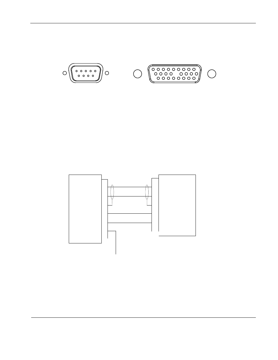
2.1. Interface Connectors
The controller connecter connects to the RosenView LX/MX connector.
2.2. RS-485 Data Bus Method Wiring Diagram
To connect the Briefing Controller using an RS-485 bus, wire the pins as shown below. This
figure is a partial view of the connector and shows only the pins used. For complete pinout
information, see the Outline and Installation drawing (P/N 0300-412-CD).
RS-485 A Output
RS-485 B Output
GND
IR +5V Output
IR Ground
15
16
17
22
24
0-5V Cockpit
Dimming Signal
RosenView LX
P/N 0603-001
RosenView MX
P/N 0603-003
RosenView
Briefing Controller
P/N 0300-412
J2 Connector
RosenView LX/MX
Briefing Controller
RS-485 communication
1
2
3
4
5
6
RS-485 A In
RS-485 B In
RS-485 Shield
+5V
5V Return
Cockpit Dim
Figure 1 RS-485 bus pinout
1
10
19
9
18
26
9
6
0
0
0
0
0
0
0
0
0
0
0
5
1
Briefing Controller interface
connector
RosenView LX/MX
J2 interface connector
Note: Not all
pins are shown