Thermo Pride Direct Vent Kit User Manual
Page 2
Page 2
INSTALLATION OF FDVS DIRECT VENT SYSTEM
I
NSTALLATION
O
F
T
HE
V
ENT
T
ERMINATION
1. Remove vent system components from box and inspect for damage. If the carton
has been crushed or mutilated, check components very carefully for damage. DO
NOT install if any damage is apparent.
2. Remove the combustion air tee assembly from the vent termination. Set the tee
aside for later use.
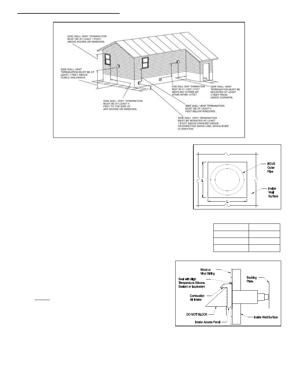
3. Refer to the appliance manufacturer’s specifications for vent termination location.
The location of the vent termination must be installed with the manufacturer's
recommendations, and/or local codes that are applicable. In the USA according
to the latest version of the National Fire Protection Association NFPA-31,
National Fuel Gas Code ANSI Z223.1. Where requirements for venting standards
differ the most stringent standard shall apply. In Canada according to the latest
version of CSA B140 and the CSA B139 Installation Code. Refer to the following
requirements or See Diagram A for typical locations.
a. The exit termination of mechanical draft systems shall not be less than 7'
above grade when located adjacent to public walkways.
b. A venting system shall terminate at least 3' above any forced air inlet located within
10'.
c.
The venting system of other than a direct vent appliance shall terminate at least 4'
below, 4' horizontally from, or 1' above any door, window or gravity air inlet into the
building.
d. The vent termination of a direct vent appliance with an input of 50,000 BTU's per hour
or less, shall be located at least 9" from any opening through which vented gases
could enter the building. With input over 50,000 BTU's per hour, a
12" termination clearance shall be required.
e. The vent termination point shall not be installed closer than 3' from
an inside corner of an L-shaped structure.
f.
The vent termination should not be mounted directly above, or
within 3' horizontally from an oil tank vent or gas meter.
g. The bottom of the vent terminal shall be located at least 12" above
finished grade or expected snow line, which ever is greater.
4. After determining the location of the venting system termination (See
Diagram A), cut a hole in the wall sized according to “L” dimension in
Table 1. (See Figure 1)
5. Seal the back side of the base plate around the outer pipe of the vent
termination with a bead of high temperature silicone sealant. (See
Figure 2) Mount the vent termination through the wall, keeping the outer
pipe centered in the hole. (See Figure 1) Fasten the vent termination to the outside wall with appropriate fasteners. Seal the edges
of the vent termination base plate to the wall with a high-temperature silicone sealant.
6.
Mount the backing plate over the outer pipe. Fasten the backing plate to the inside wall with appropriate fasteners. (See Figure 2)
DO NOT BLOCK the intake or exhaust openings, or the intake access panel on the vent termination body. Wood or vinyl siding should
be cut so that the unit mounts directly on the wallboard to provide a stable support. If the siding is greater than 1/2" thick use a spacer
plate or board behind the vent termination mounting plate. (See Figure 2)
Diagram A
Figure 1 – End View
Figure 2 – Side View
Model
“L”
FDVS-4
7-1/4”
FDVS-5
8-1/4”
FDVS-6
9-1/4”
Table 1
(a)
(b)
(c)
(e)
(g)
(c)
(c)