Figure 2-4. set-back dimensions, 1 mounting ear installation, Mounting ear installation – KEPCO RA 60 Rev 1, 2, 3 User Manual
Page 16: Set-back dimensions -4
2-4
RA60 SERIES 090910
(b) The rack adapter can be attached to the rack using chassis slides; the rack adapter sides are
predrilled for 18" (457.2mm) chassis slides (see Table 1-2).
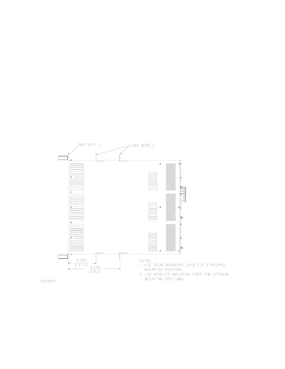
(c) For applications which require less depth protrusion of the rack adapter within the rack, the
rack adapters provide two “set-back” positions for use with optional notched mounting ears
(see Tables 1-1 and 1-2); see Figure 2-4 for set-back dimensions.
For all installations provide adequate clearance around air inlet and exhaust locations and
ensure that the temperature immediately surrounding the unit, and especially near the air inlets,
does not exceed the maximum specified ambient temperature for the operating conditions of the
installed power supplies.
CAUTION
WHEREVER POSSIBLE RACK ADAPTER SHOULD BE MOUNTED BEFORE INSTALLING
POWER SUPPLIES TO AVOID DISTORTION OF THE RACK ADAPTER (INSTALL POPU-
LATED RACK ADAPTER ONLY IF BOTTOM OF RACK ADAPTER IS FULLY SUPPORTED).
FAILURE TO OBSERVE THIS CAUTION MAY RESULT IN MISALIGNMENT OF THE POWER
SUPPLIES WITH THE RACK ADAPTER.
FIGURE 2-4. SET-BACK DIMENSIONS
2.5.1
MOUNTING EAR INSTALLATION
If mounting ears are removed, or optional mounting ears are purchased to allow installation in a
different size rack, install each standard (unnotched) mounting ear with spacer (part number
128-1716) between the mounting ear and the inside surface of the rack adapter chassis (see