Purdy AND-TFT-5VX-KIT User Manual
Displays, And-tft-5vx-kit, Features
Displays
Purdy Electronics Corporation • 720 Palomar Avenue • Sunnyvale, CA 94085
05/13/03
Tel: 408.523.8200 • Fax: 408.733.1287 • [email protected] • www.purdyelectronics.com
1
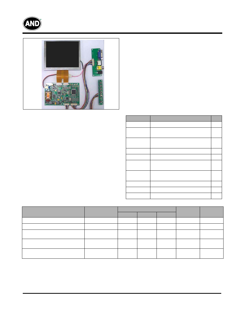
AND-TFT-5VX-KIT
640 x 480 Pixels
LCD Color Monitor
The AND-TFT-5VX-KIT is a compact full color TFT LCD
module, whose driving board is capable of converting
composite video signals to the proper interface of LCD panel
and is suitable for computer peripheral, industrial meter,
image communication and multi media.
This device consists of an amorphous silicon panel with
back-light, incorporating a TFT-array that has 640 x 480
pixels on a 5 inch diagonal screen, with pixel in stripe
configuration, 262,144 display colors and a TTL transmission
interface.
Features
• VGA (640 x 480 pixels) resolution
• Amorphous silicon TFT LCD panel with back-lit unit
• Pixel in stripe configuration
• Light weight and slim
• Displays 262,144 colors
• Optimum Viewing Direction: 6 o’clock
•
Portrait mode
• TTL transmission interface
Mechanical Characteristics
Parameter
Specification
Unit
Screen Size
5.0 (diagonal)
inch
Display
Format
640 (H) x (R, G, B) x 480(V)
dot
Display
Colors
262,144
Active Area
74.88 (H)x101.76(V)
mm
Pixel Pitch
0.156(H)x0.159(V)
mm
Pixel
Configuration
Stripe
Outline
Dimension
91.4(H)x119.3(V)x7.9(D)
mm
Weight
120±10
g
Back-light
CCFL, 1 tube
Diplay Mode
Normally white
Product specifications contained herein may be changed without prior notice. It is therefore advisable to contact
Purdy Electronics before proceeding with the design of equipment incorporating this product.
Recommended Driving Condition for Back Light
Ta=25ºC
Parameter
Symbol
Specifications
Unit
Remark
Min.
Typ.
Max.
Lamp Voltage
V
L
390
410
430
V
I
L
=6mA
Lamp Current
I
L
4.0
6.0
8.0
mA
Note 1
Lamp Frequency
P
L
30
45
60
KHZ
Note 2
Starting Voltage (25ºC)
(Reference Value)
Vs
–
–
640
Vrms
Note 3
Starting Voltage (0ºC)
(Reference Value)
Vs
–
–
740
Vrms
Note 3
Note 1 : In order to satisfy the quality of B/L, no matter what inverter is used, the output lamp current must be between
Min. and Max. to avoid the abnormal display image caused by B/L.
Note 2 : The waveform of lamp driving voltage should be as close to a perfect sine wave as possible.
Note 3 : The “Max of starting voltage” means the minimum voltage of inverter turns on the CCFL and it should be applied to
the lamp for more than 1 second to start up. Otherwise the lamp may not be turned on.
• RoHS Compliant
Part List
• AND-TFT-5VX
• PC-TFT-5VX
• 6 Button OSD board with cable
• User interface board with cable