Maintenance procedures – SAF-HOLLAND XL-FW10049OM AL Aluminum NoLube Series Fifth Wheels User Manual
Page 16
16
XL-FW10049OM-en-US Rev A 11-10 Amendments and Errors Reserved. © SAF-HOLLAND, Inc.
Figure 26
Maintenance Procedures
Failure to maintain proper
fifth wheel adjustment
could result in loss of
vehicle control which, if not
avoided, may result in
death or serious injury.
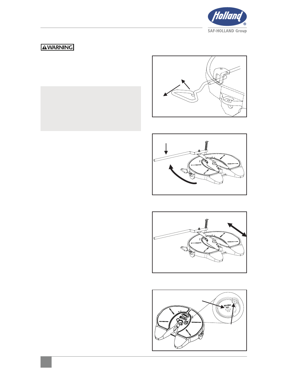
1. If
fifth
wheel
is
locked, slide release
handle forward and pull all the way
out (Figure 26). If air release
equipped, actuate fifth wheel control
valve to open lock.
2.
Set lock tester on fifth wheel top
plate .
3.
To lock fifth wheel, rotate handle on
lock tester clockwise until the locks
close around the kingpin (Figure
27).
4.
Slide the lock tester forward and
backward in the closed lock to check
for play between lock and kingpin.
Ensure that the tool remains flat with
full contact on the fifth wheel top
plate. Use pin gage to measure free
play. If free play exceeds 0.080”,
adjust lock mechanism (Figure 28).
5.
To adjust lock, unscrew the low head
socket cap screw until the head
clears the adjusting pin and rotate
adjusting pin counter-clockwise until
the next notch lines up with the low
head socket cap screw. Re-tighten
low head socket cap screw. Adjust
only one notch at a time (Figure 29).
NOTE: To obtain proper fifth wheel
adjustment SAF-HOLLAND
recommends use of Holland lock
tester Part No. TF-TLN-5001,
available from your local Holland
distributor.
Figure 27
Figure 28
ADJUSTING
PIN
LOW HEAD
SOCKET CAP
SCREW
Figure 29
TF-TLN-5001
SLI
DE
FO
RW
AR
D
PU
LL O
UT ALL
THE WAY