Kingpin installation, Lift with a threaded handle (item no. 31 on pg 3) – SAF-HOLLAND XL-FW445-01 FW0001 Series Fifth Wheel User Manual
Page 4
4
XL-FW445-01
Copyright © July 2003 • The Holland Group, Inc.
Holland USA, Inc. Facilities:
Dumas, AR
Warrenton, MO
Holland, MI
Wylie, TX
Muskegon, MI
Ph: 888-396-6501
Fax: 800-356-3929
Holland International, Inc.
Holland, MI
Phone:
616-396-6501
Fax:
616-396-1511
Holland Equipment, Ltd.
Norwich, Ontario • Canada
Phone:
519-863-3414
Fax:
519-863-2398
Holland Hitch Western, Ltd.
Surrey, British Columbia • Canada
Phone:
604-574-7491
Fax:
604-574-0244
Holland Hitch of Canada, Ltd.
Woodstock, Ontario • Canada
Phone:
519-537-3494
Fax:
800-565-7753
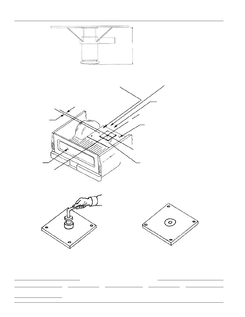
KINGPIN INSTALLATION
6.625˝
3˝ to 9˝
CL
CL
CL
Axle
Tailgate
Truck
Kingpin
(4) struc. bolts must go through the 1/4˝
plate, floor, and existing holes in the truck
frame. Secure with self lock nuts.
(Furnished by the customer.)
Cut a 9˝ square hole at the center
lines, through the 1/4˝ plate and floor.
Insert the lower part of the kingpin
assembly into the 9˝ square hole.
Make sure that the pipe plug is on
the side of the kingpin housing that
points toward the cab of the truck.
1/4˝ min. plate, approx. 36˝ wide x 50˝ long.
(Supplied by the customer.)
In some applications, additional support may be
required under the bed.
Minimum of 6˝ of weld on each of 4
corners and use (4) 1/2˝ dia. grade
5 carriage bolts and self lock nuts.
TO RAISE
Lift with a threaded handle
(item no. 31 on pg 3)
TO RETRACT
Step on the kingpin with your
foot. Do not use hands.
Allowable clearance for the
kingpin storage position.