Installation procedures, Caution – SAF-HOLLAND XL-FW376-01 Electronic Lock Indicator For XA-351 and XA-331 Series Fifth Wheel Top Plates with Holland factory-installed sensors User Manual
Page 2
2
INSTALLATION PROCEDURES
continued
6. Drill a
13
/
16
˝ diameter utility hole in the cab
making sure that there are no obstructions
near the drilling area.
7. Run the end (A) of the extension cable with the
power wires (see FIGURE 1), through the utility
hole and into the cab.
8. Install the 1-amp fuse (see FIGURE 4):
a. Strip 3/8˝ of insulation from the RED
extension cable power wire and from
the tractor’s positive (+) power wire. It is
recommended that a switched terminal in
the main fuse box be used so that power is
supplied when the ignition is turned on.
b. Insert the wires into each end of the
fuse holder.
c.
Crimp each terminal through the fuse
holder body.
9. Connect the two power wires from the 25´
extension cable to a 12- or 24-volt power
supply. (The back of each display box is
marked with 12- or 24-VDC.) Be sure to
connect the RED wire with the fuse —
as outlined in STEP 8 — to the positive (+)
terminal, and the BLACK wire to the ground
(-) terminal.
10. Connect the 25´ extension cable to the
ELI display box cable inside the cab.
11. Press the grommet into position in the utility
hole. Apply sealant to the grommet and
extension cable to prevent moisture intrusion
into the cab.
3/8˝
3/8˝
STRIPPED WIRE
INSERT
INSERT
CRIMP HERE
RED EXTENSION
CABLE POWER WIRE
ATTACH POSITIVE(+) POWER
WIRE TO A SWITCHED TERMINAL
IN THE MAIN FUSE BOX.
FIGURE 4
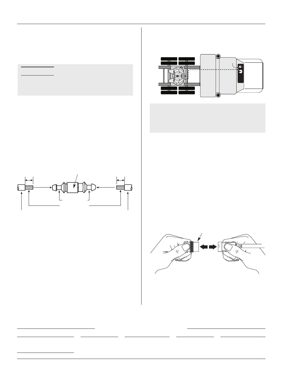
12. Route the 25´ extension cable from the cab to
the fifth wheel. See FIGURE 5.
13. Route the wire clear of pinch points.
NOTE: For sliding fifth wheels, be sure to leave
enough slack for travel and route the
wire clear of pinch points. It can be
helpful to route the wire through an
existing coiled air line.
14. Secure the extension cable so that it is free of
interference from the fifth wheel articulation,
brake lines, light cord, drive line etc.
15. Remove and discard the protective plug from
the connector at the end of the fifth wheel
sensor harness as shown in FIGURE 6.
16. Connect the 25´ extension cable to the sensor
harness on the fifth wheel.
17. Check the operation of the fifth wheel and the
Electronic Lock Indicator using lock adjustment
tool TF-TLN-5001.
For operating instructions, see Holland publication
XL-FW389-XX.
FUSE HOLDER
CAUTION
12V
FIGURE 5
DISCARD
FIGURE 6
Failure to connect a voltage
source that matches the
specification on the box will
result in a damaged and
inoperable display box.
Copyright © September 2002 • The Holland Group, Inc.
Holland USA, Inc. Facilities:
Denmark, SC
Warrenton, MO
Dumas, AR
Whitehouse Station, NJ
Holland, MI
Wylie, TX
Muskegon, MI
Ph: 888-396-6501
Fax: 800-356-3929
Holland International, Inc.
Holland, MI
Phone:
616-396-6501
Fax:
616-396-1511
Holland Equipment, Ltd.
Norwich, Ontario • Canada
Phone:
519-863-3414
Fax:
519-863-2398
Holland Hitch Western, Ltd.
Surrey, British Columbia • Canada
Phone:
604-574-7491
Fax:
604-574-0244
Holland Hitch of Canada, Ltd.
Woodstock, Ontario • Canada
Phone:
519-537-3494
Fax:
800-565-7753