SAF-HOLLAND XL-FW152-03 FW67 Series Air Lift Fifth wheel User Manual
Page 2
2
C. Install all air hoses and fittings as shown
on the piping diagram (see Figure 4) for
model (FW67 or FW69 series) selected. Use
care to assure that all hoses and fittings
are clean and free from foreign material
and that all joints are properly sealed.
3.
Fifth Wheel Lock Control
Valve Installation:
A. Install fifth wheel lock control valve in a
location in the cab where it will not be
accidentally activated.
B. Connect the air supply for the lock
control where the chassis manufacturer
recommends. Hose and fittings for these
connections are to be supplied by the
customer/installer. See
Figure 4 for
plumbing diagram.
4.
System Check:
A. Double check the fifth wheel installation:
1. Are the fittings tight?
2. Are all mounting bolts
properly tightened?
3. Is the fifth wheel frame properly
welded to the mounting angles?
B. Lubricate the unit. Apply grease to the
top bearing surface of the fifth wheel and
grease all grease zerks at pivot points in
the elevating fifth wheel mechanism.
C. Review the operating instructions
(Holland publication XL-FW344-XX) and
place them in the tractor cab.
D. Check the proper operation of the fifth
wheel locking mechanism by coupling
several times to a trailer or with a
HOLLAND TF-TLN-5001 Lock Tester
(the lock tester may be used prior to
greasing the top plate.)
E. Check the operation of the lifting system
— in accordance with the operating
instructions — by lifting, moving,
and spotting a trailer.
F.
Shut the system down and check the
air system for leaks. Also, examine the
mechanical components to assure that
there are no interferences with any
components of the tractor frame.
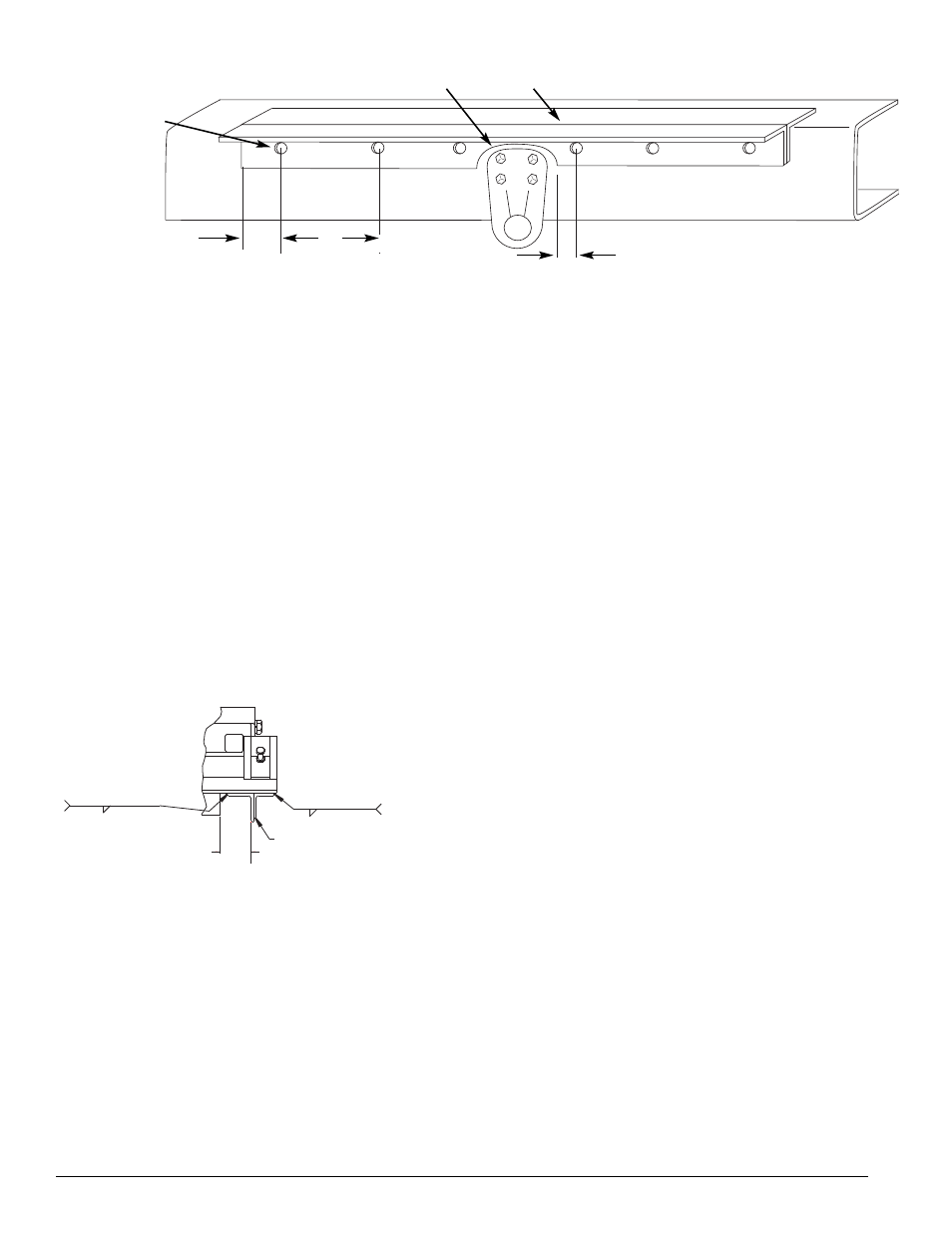
Angle cut out for tractor frame
interference. 1˝ minimum for radius.
1˝ minimum
from hole to
the end of
the angle.
Holes drilled for
5
/
8
˝ mounting bolts.
Lift wheel
mounting base
1˝ – 1
1
/
2
˝ Mounting required between
1˝ and 1
1
/
2
˝ of angle cut out.
8˝
Maximum
hole spacing
D. Remove and cut the mounting angles as
required. Use a 1˝ minimum radius for all
cut outs and then grind smooth.
E. Clamp the mounting angles tightly to the
tractor frame. Check clearances and cut outs.
Locate and drill for
5
/
8
˝ mounting bolts with
a maximum spacing of 8˝. The bolts should
be located between 1˝ to 1
1
/
2
˝ of each cut
out. (See Figure 2.)
F.
Position the elevating fifth wheel on the
“T” style mounting angles with the top plate
pivot on the marked location. Verify that
there are no interferences. Tack weld the
mounting angle to the elevating fifth wheel.
G. Remove the fifth wheel from the tractor and
complete the welding of the mounting angles
to the fifth wheel frame as shown in Figure 3.
Make
5
/
16
˝ fillet welds inside and outside with
skip welds 3˝ long on approximately 8
1
/
2
˝
centers (weld 3˝, skip 5
1
/
2
˝). Weld inside
opposite welds on the
outside (see Figure 3). Also weld the frame to
the top of the angle at the ends of the frame.
H. Reposition the fifth wheel assembly on
the tractor and install using Grade 8,
5
/
8
˝
diameter bolts, hardened steel washers
and lock nuts in all holes that were drilled.
Torque the bolts to the bolt manufacturer’s
specifications.
2.
Air Component Installation:
A. Install the air tank.
B. Install the three-way fifth wheel lift control
valve in a location in the cab where it will
not be accidentally activated.
FIGURE 2
REF
4-
1
/
4
”
3”-8-
1
/
2
”
5
/
16
”
"T" STYLE MOUNTING ANGLE
(For 34" Frame width mount
angle with the 2
1
/
2
" x 3
1
/
2
"
angle to the outside)
3”-8-
1
/
2
"
5
/
16
”
FIGURE 3