Whelen MBFX11AA User Manual
Page 2
Page 2
Fig. 4
ION™
LIGHTHEAD
#6 X 1 PPHSMS
#8 X 1/2"
PHILLIPS
T R U S S
S C R E W
#8 SCREW
GROMMET
GASKET
BUSHING
Exits mirror
assembly
base
Mirror-Beam™
HOUSING
Position connectors between Mirror-Beam™ housing and mirror assembly housing
Exits front
of mirror
assembly
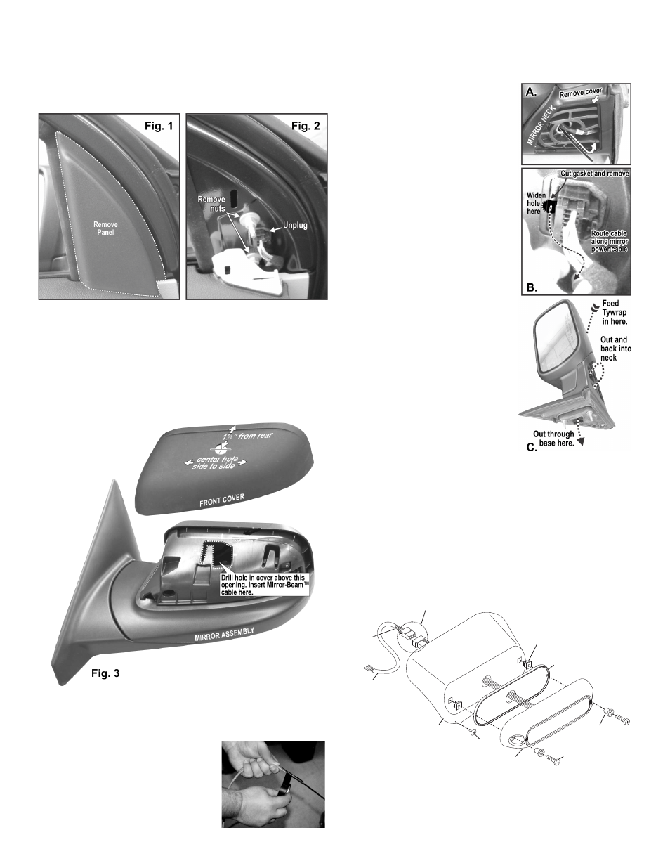
To Remove the Side Mirror Assembly:
1.
Remove the triangular panel from the inside of the door that covers
the mirror assembly base (Fig. 1). This panel snaps in.
2.
Remove the two nuts holding the mirror assembly on, unplug the
wiring and remove the mirror assembly from the vehicle (Fig. 2).
Preparing Mirror Assembly:
1.
Remove the mirror assembly cover from the front of the mirror
assembly. The cover snaps off. Carefully push the cover forward
away from the mirror to remove it.
2.
Mark off the wire hole location on the top of the cover, measuring 1-1/
2” from the rear (mirror side) and at the approximate center from left
to right (Fig. 3). The wire hole must be located over the hole in the
mirror assembly that the Mirror-Beam™ cable will exit. Drill the wire
hole through the cover using a 3/4” drill.
Preparing the Mirror-Beam™ cable:
Because the Mirror-Beam™ cable must be routed through a specific,
narrow and twisting path within the mirror assembly, it will be
necessary to temporarily extend the
length of the cable.
1.
Locate the ty-wrap (included) and cut
the fastener-end off.
2.
Locate the end of the cable that has
PIN-type terminals installed on the
wires. Cut off the non-insulated wire (not
used).
3.
Strongly secure the ty-wrap to the cable with electrical or similar tape.
It is important to have a sufficient length of the ty-wrap secured to the
cable (2” minimum) (Fig. 4).
Routing Mirror-Beam™ Cable:
1.
Insert the ty-wrap into the front of the
mirror assembly (Fig. 3). Remove the
small cover that snaps on and off,
covering the wiring on the mirror
neck. Continue to push the ty-wrap in
until the end of the ty-wrap sticks out
of the mirror neck (A). Pull the ty-wrap
out until slack in the cable is gone.
There should not be more than 4 - 5”
of cable sticking out of the front of the
mirror assembly.
2.
Feed the ty-wrap back into the mirror
assembly neck (along the mirror
power cables path) and back out
through the hole in the mirror
assembly base that the mirror power
cable connector occupies (B & C).
You will have to cut out a small
amount of the outside of the base
gasket to accommodate the Mirror-
Beam™ cable. You may have to
widen the connectors hole with a
round file if the cable doesn’t fit (B).
3.
Insert the end of the cable into the
1/2” hole you drilled in the mirror
assembly cover and snap the cover
back onto the mirror assembly.
4.
Remove the ty-wrap from the cable.
Install the socket connector (supplied)
onto the end of the cable coming out
of the front of the mirror assembly.
(see wiring diagram).
Affixing Mirror-Beam™ Housing to Mirror Assembly:
1.
Reconnect the mirror power cable and remount the mirror assembly
onto the vehicle using the original hardware. Route the Mirror-
Beam™ cable through the door, along the same path as the vehicle’s
main power harness. Make sure that neither of the harness cables
are crimped or pinched. Tighten all nuts firmly and reattach the panel
covering the mirror assembly base.
2.
Mount the lighthead to the Mirror-Beam™ housing and plug the
lighthead into the connector coming from the front of the mirror
assembly. This connection will be tucked between the Mirror-Beam™
housing and the mirror assembly (Fig. 4).
3.
NOTE: The following procedure requires that the mirror
assembly be no colder than 60°F (18°C). Thoroughly clean the
plastic mirror assembly and the inside surface of the Mirror-Beam™
housing using a 50/50 mixture of isopropyl (not rubbing) alcohol and
water. Dry completely.
Fig. 4