Whelen SK02V3AA User Manual
Page 2
Page 2
SignalAlert™ 75 / phase 1
SignalAlert™ 75 / phase 2
CometFlash® 75 / phase 1
CometFlash® 75 / phase 2
DoubleFlash 75 / phase 1
DoubleFlash 75 / phase 2
SingleFlash 75 / phase 1
SingleFlash 75 / phase 2
ComAlert™ 75 / phase 1
ComAlert™ 75 / phase 2
LongBurst™ 75 / phase 1
LongBurst™ 75 / phase 2
PingPong™ 75 / phase 1
PingPong™ 75 / phase 2
1.
2.
3.
4.
5.
6.
7.
8.
9.
10.
11.
12.
13.
14.
Flash Patterns (SYNC)
SingleFlash 60
SingleFlash 90
SingleFlash 120
SingleFlash 300
DoubleFlash 150
ComAlert™ 150
ActionFlash™ 50
ActionFlash™ 150
ModuFlash™
ActionScan™
Steady
19.
20.
21.
22.
23.
24.
25.
15.
16.
17.
18.
Flash Patterns (NON SYNC)
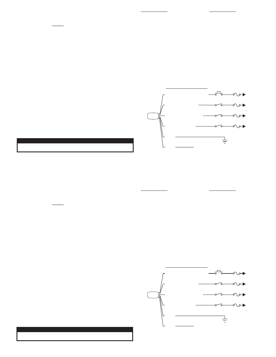
Light
BLK
GRY
WHT/VIO (Scan-Lock)
RED (Warning)
WHT/RED (
)
Puddle
WHT/BLK (
)
Alley
SP/ST
SP/ST
SP/ST
Mom. SW
1 Amp
3 Amp
1 Amp
3 Amp
+12VDC
+12VDC
+12VDC
+12VDC
To Chassis Ground
To SYNC wire of other SYNC capable light
WIRING DIAGRAM
Wiring:
WARNING: All customer supplied wires that connect to the positive terminal
of the battery must be sized to supply at least 125% of the maximum
operating current and FUSED at the battery to carry that load.
DO NOT USE CIRCUIT BREAKERS WITH THIS PRODUCT!
Ground (BLK) - Extend to chassis ground.
Warning Light (RED) - Extend to +12VDC via an SP/ST switch (fuse @ 3A).
Alley Light (WHT/BLK) - Extend to +12VDC via an SP/ST switch (fuse @ 3A).
Puddle Light (WHT/VIO) - Extend to +12VDC via an SP/ST switch (fuse @ 1A).
Scan-Lock (GRY) - Extend to +12VDC via an MOM switch (fuse @ 1A).
SYNC (GRY) - See below.
Operation:
Scan-Lock™ - Note: The light must be on to change patterns.
To advance to next pattern: Apply +VDC to the WHT/VIO wire for less than 1
second.
To cycle backwards: Apply +VDC to the WHT/VIO wire for more than 1 second.
To reset to the factory default pattern: Turn off power to the light. While
applying +VDC to the WHT/VIO wire, turn the light back on. Continue to apply
voltage for 5 seconds.
SYNC - Lights configured to display the Phase 1 mode of a pattern will flash
simultaneously. Lights configured to display the Phase 2 mode will alternate with any
Phase 1 lights with the same pattern.
To sync two lights, configure both lights to display the same Phase 1 pattern. Turn
power off and connect the GREY wires from each light together. When the lights are
activated, their patterns will be synchronized. To configure the two lights to alternate
their patterns, advance the pattern of either lights to Phase 2 of the current pattern.
CAUTION! DO NOT LOOK DIRECTLY AT THESE LED’S WHILE THEY ARE ON.
MOMENTARY BLINDNESS AND/OR EYE DAMAGE COULD RESULT!
I M P O R TA N T W A R N I N G !
SignalAlert™ 75 / phase 1
SignalAlert™ 75 / phase 2
CometFlash® 75 / phase 1
CometFlash® 75 / phase 2
DoubleFlash 75 / phase 1
DoubleFlash 75 / phase 2
SingleFlash 75 / phase 1
SingleFlash 75 / phase 2
ComAlert™ 75 / phase 1
ComAlert™ 75 / phase 2
LongBurst™ 75 / phase 1
LongBurst™ 75 / phase 2
PingPong™ 75 / phase 1
PingPong™ 75 / phase 2
1.
2.
3.
4.
5.
6.
7.
8.
9.
10.
11.
12.
13.
14.
Flash Patterns (SYNC)
SingleFlash 60
SingleFlash 90
SingleFlash 120
SingleFlash 300
DoubleFlash 150
ComAlert™ 150
ActionFlash™ 50
ActionFlash™ 150
ModuFlash™
ActionScan™
Steady
19.
20.
21.
22.
23.
24.
25.
15.
16.
17.
18.
Flash Patterns (NON SYNC)
Light
BLK
GRY
WHT/VIO (Scan-Lock)
RED (Warning)
WHT/RED (
)
Puddle
WHT/BLK (
)
Alley
SP/ST
SP/ST
SP/ST
Mom. SW
1 Amp
3 Amp
1 Amp
3 Amp
+12VDC
+12VDC
+12VDC
+12VDC
To Chassis Ground
To SYNC wire of other SYNC capable light
WIRING DIAGRAM
Wiring:
WARNING: All customer supplied wires that connect to the positive terminal
of the battery must be sized to supply at least 125% of the maximum
operating current and FUSED at the battery to carry that load.
DO NOT USE CIRCUIT BREAKERS WITH THIS PRODUCT!
Ground (BLK) - Extend to chassis ground.
Warning Light (RED) - Extend to +12VDC via an SP/ST switch (fuse @ 3A).
Alley Light (WHT/BLK) - Extend to +12VDC via an SP/ST switch (fuse @ 3A).
Puddle Light (WHT/VIO) - Extend to +12VDC via an SP/ST switch (fuse @ 1A).
Scan-Lock (GRY) - Extend to +12VDC via an MOM switch (fuse @ 1A).
SYNC (GRY) - See below.
Operation:
Scan-Lock™ - Note: The light must be on to change patterns.
To advance to next pattern: Apply +VDC to the WHT/VIO wire for less than 1
second.
To cycle backwards: Apply +VDC to the WHT/VIO wire for more than 1 second.
To reset to the factory default pattern: Turn off power to the light. While
applying +VDC to the WHT/VIO wire, turn the light back on. Continue to apply
voltage for 5 seconds.
SYNC - Lights configured to display the Phase 1 mode of a pattern will flash
simultaneously. Lights configured to display the Phase 2 mode will alternate with any
Phase 1 lights with the same pattern.
To sync two lights, configure both lights to display the same Phase 1 pattern. Turn
power off and connect the GREY wires from each light together. When the lights are
activated, their patterns will be synchronized. To configure the two lights to alternate
their patterns, advance the pattern of either lights to Phase 2 of the current pattern.
CAUTION! DO NOT LOOK DIRECTLY AT THESE LED’S WHILE THEY ARE ON.
MOMENTARY BLINDNESS AND/OR EYE DAMAGE COULD RESULT!
I M P O R TA N T W A R N I N G !