Whelen SAK11 User Manual
Au to mo tiv e: sirens & switches, Au tom o tive : sirens & switches, Caution
Page 1
©2007 Whelen Engineering Company Inc.
Form No.14123A (050708)
Installation Guide:
SA315 Speaker Bracket
2002 Trailblazer
®
ENGINEERING COMPANY INC.
Internet: www.whelen.com
Sales e-mail: [email protected]
Canadian Sales e-mail: [email protected]
Customer Service e-mail: [email protected]
For warranty information regarding this product, visit www.whelen.com/warranty
51 Winthrop Road,
Chester, Connecticut 06412-0684
Phone: (860) 526-9504
Fax: (860) 526-4078
Au
to
mo
tiv
e:
Sirens & Switches
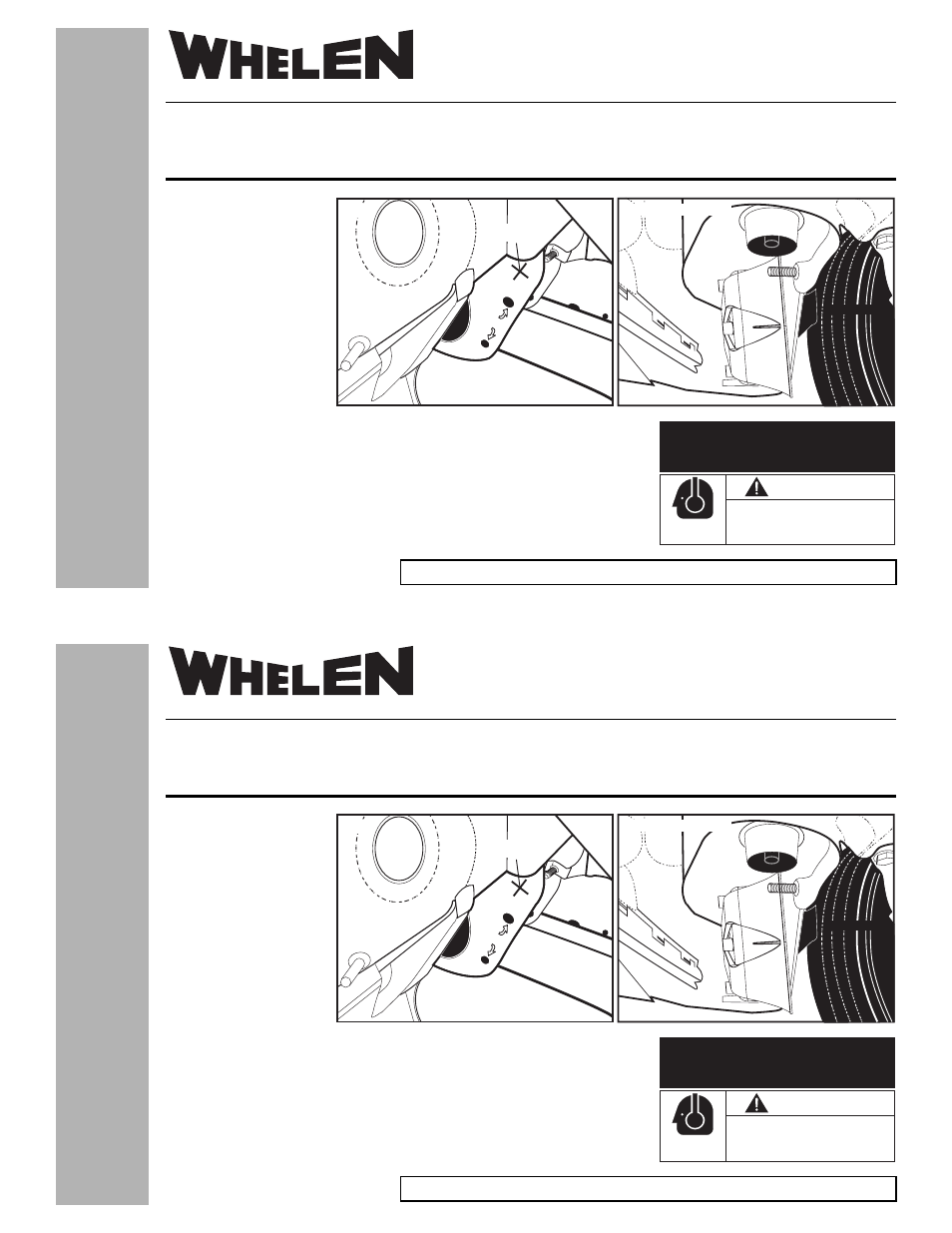
Installation:
1.
Secure the speaker to
the bracket using the
supplied mounting
hardware (see next
page).
2.
On the lower radiator
support, find the
existing holes shown in
Figure 1. Using the
supplied mounting
hardware, mount the
bracket (with speaker
attached) to the lower
radiator support as shown in Figure 2.
3.
Installation is complete and the speaker is ready to connect to power. Extend the
WHITE (Positive) and BLACK (Negative) speaker wires to your siren amplifier and
connect as shown in the amplifiers instructions.
NOTE: The bracket can be mounted to either side of the vehicle. Mounting is
identical, except the bracket will face the opposite way.
FRAME
RAIL
MOUNTING
HOLES
SIREN
Fig. 1
Fig. 2 Passenger Side
RADIATOR
SUPPORT
FRONT TIRE
CAUTION
Loud siren noise can cause
hearing damage and/or loss.
Refer to OSHA Section 1910.95 prior
to putting ANY siren into service!
Wear
Protection!
ACTIVATION OF THIS
SIREN MAY DAMAGE
UNPROTECTED EARS!
©2007 Whelen Engineering Company Inc.
Form No.14123A (050708)
Installation Guide:
SA315 Speaker Bracket
2002 Trailblazer
®
ENGINEERING COMPANY INC.
Internet: www.whelen.com
Sales e-mail: [email protected]
Canadian Sales e-mail: [email protected]
Customer Service e-mail: [email protected]
For warranty information regarding this product, visit www.whelen.com/warranty
51 Winthrop Road,
Chester, Connecticut 06412-0684
Phone: (860) 526-9504
Fax: (860) 526-4078
Au
tom
o
tive
:
Sirens & Switches
Installation:
1.
Secure the speaker to
the bracket using the
supplied mounting
hardware (see next
page).
2.
On the lower radiator
support, find the
existing holes shown in
Figure 1. Using the
supplied mounting
hardware, mount the
bracket (with speaker
attached) to the lower
radiator support as shown in Figure 2.
3.
Installation is complete and the speaker is ready to connect to power. Extend the
WHITE (Positive) and BLACK (Negative) speaker wires to your siren amplifier and
connect as shown in the amplifiers instructions.
NOTE: The bracket can be mounted to either side of the vehicle. Mounting is
identical, except the bracket will face the opposite way.
FRAME
RAIL
MOUNTING
HOLES
SIREN
Fig. 1
Fig. 2 Passenger Side
RADIATOR
SUPPORT
FRONT TIRE
CAUTION
Loud siren noise can cause
hearing damage and/or loss.
Refer to OSHA Section 1910.95 prior
to putting ANY siren into service!
Wear
Protection!
ACTIVATION OF THIS
SIREN MAY DAMAGE
UNPROTECTED EARS!