Whelen 7087501 User Manual
Aviation
Page 1
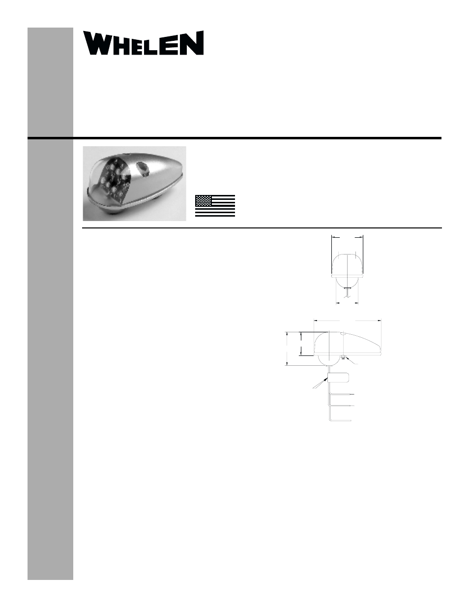
3.92
1.83
2X #6 HEX NUT
(FOR SHIPPING ONLY)
Wires shown for
reference only.
See reverse for
wiring information.
1.35
2.02
1.39
MFG LABEL
The conditions and tests required for TSO approval of this
article are minimum performance standards. It is the
responsibility of those installing this article either on or
within a specific type or class of aircraft to determine that
the aircraft installation conditions are within the TSO
standards. TSO articles must have separate approval for
installation in aircraft. The article may be installed only if
performed under 14 CFR part 43 or the applicable
airworthiness requirements.
®
ENGINEERING COMPANY INC.
Route 145, Winthrop Road,
Chester, Connecticut 06412
Phone: (860) 526-9504
Fax: (860) 526-2009
Internet: www.whelen.com
Sales/Service e-mail: [email protected]
Aviation
Installation Guide:
Model 70875( )-series
Models 7087501,7087502,7087503,7087504
P/N: 01-0770875-01, -02, -03, -04
LED Forward Position
Light Assembly
©2003 Whelen Engineering Company Inc.
Form No.13777E (041505)
TSO-C30c
TYPES I & II
APPROVED
MADE IN THE U.S.A.
OPERATING INSTRUCTIONS:
Operational Voltage: . . . . . . . . .28 VDC
Average Input Current: . . . . . . .0.35 Amps
EQUIPMENT LIMITATIONS: An approved forward
position lighting system consists of two lights, one located
on each wingtip, mounted at a minimum of 4” from the
leading edge.
CONTINUED AIRWORTHINESS: The 70875 series LED
wingtip position light assembly is designed with 7 LED’s. If
any one LED fails, the unit must be repaired or replaced.
INSTALLATION PROCEDURES: The following
information is to assist in the installation of a Whelen LED
Forward Position Light System.
1.
Choose the appropriate 70875( ) series replacement
light assembly.
2.
The installation procedure described in the
following text will be confined to a single light
installation, but is identical for multiple light
installations.
3.
Remove the old light, locate and save the existing
+28VDC lead and (-) ground lead. Clean and prep
ends as required.
4.
Make sure the existing system is equipped with an
appropriate sized breaker. Connect the existing
+28VDC lead to the 18 AWG wire on the input cable
assembly (supplied with the light assembly). Connect
the existing ground lead to the black 18 AWG wire on
the input cable assembly. Both leads must be
connected by an approved FAA connection. Insure
that the wire leads and the pressure venting tube are
all clear of any obstructions and ty-wrap as required.
The pressure venting tube may be trimmed to a
minimum length of 1” from the base.
5.
Remove the two #6-32 x 1¼” screws and remove
lens from the LED position light assembly. Retain the
screws and discard the hex nuts.
6.
Position the base of the new light assembly onto the mounting
surface. Insert a #6-32 PPHMS from the previously installed
assembly into the rear-most mounting hole and tighten firmly.
7.
Secure the lens onto the base with the #6-32 x 1¼" screws
referenced in step 5. Tighten these screws until lens bosses
bottom on the LED module.
8.
Check all avionics systems for interference from the installation.
9.
A flight check should be performed by a properly certified pilot.
10. When necessary, waterproof the assembly to aircraft. Apply
aviation approved single part silicone (RTV) or equivalent
around any open area where water could get in.
11.
Update aircraft records, complete Form 337 and obtain FAA
field approval for installation.