Whelen 9020609 User Manual
Aviation, Engineering company inc
Page 1
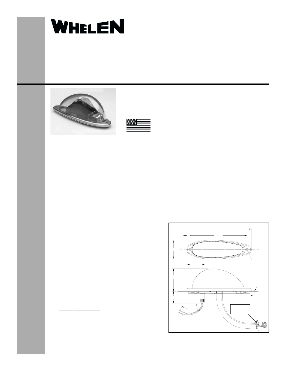
10.63
.51
3.06
1.97
3.75
1.6
22”
APPROX.
26”
APPROX.
MS 3106F-10SL-3P
3 PIN CONNECTOR
LENS RETAINER
MOUNTING SCREW
(2) PLACES
EXISTING
MTG
PLATE
WINGTIP
SKIN
9.375
FORWARD POSITION LIGHT
BLACK (GROUND)
WHITE (POSITIVE)
A - ANODE
B - TRIGGER
C - CATHODE
®
ENGINEERING COMPANY INC.
Route 145, Winthrop Road,
Chester, Connecticut 06412
Phone: (860) 526-9504
Fax: (860) 526-2009
Internet: www.whelen.com
Sales/Service e-mail: [email protected]
Aviation
Installation Guide
Aviation model 9020609,9020610
P/N 01-0790206-09, 01-0790206-10
Anti-Collision/LED Position Light Ass’y
©2006 Whelen Engineering Company Inc.
Form No.14022 (021406)
SPECIFICATIONS:
Nominal Operational Voltage: ........28 VDC
Input Current: ..................................0.3 AMP
Total Weight .....................................1.97 lbs.
EQUIPMENT LIMITATIONS:
An approved Anti-Collision / Position System consists
of assembly 90206( ) and strobe power supply
9010104, located on each wingtip.
CONTINUED AIRWORTHINESS:
The LED position light is designed with 5 LED’s. If any
one LED fails, the unit must be repaired or replaced.
Inspect the lens for excessive scratches or pitting.
Replace if necessary.
INSTALLATION PROCEDURES:
The following information is to assist you in installing a
Whelen Anti-Collision / Position light system.
1.
Choose the appropriate Model 90206 - ( )
replacement light assembly.
2.
The installation procedure described in the
following text will be confined to a single light
installation, but is identical for multiple light
installation.
3.
Remove old anti-collision light, locate and record
existing +28 VDC and (-) ground position and
output connector from power supply.
4.
Use existing mounting holes and hardware.
5.
Connect leads from light assembly in recorded
manner and lead from light to power supply.
6.
Breaker Requirements
Make sure existing system is equipped with an
appropriate sized breaker.
7.
Install light assembly and insure that all leads are
clear of any obstructions and ty-rap as required.
Secure light assembly, use lock washers and/or
thread lock, on all threaded fasteners.
8.
Check all avionics systems for interference from
this installation.
9.
A flight check should be performed by a properly
certified pilot.
10. When necessary, waterproof the light assembly to
aircraft. Apply single part silicone (RTV) or
equivalent around any open area where water
could get in.
11. Update aircraft records and complete Form 337.
12. Obtain FAA field approval for installation.
MADE IN THE U.S.A.
The conditions and tests required for TSO approval of this
article are minimum performance standards. It is the
responsibility of those installing this article either on or
within a specific type or class of aircraft to determine that
the aircraft installation conditions are within the TSO
standards. TSO articles must have separate approval for
installation in aircraft. The article may be installed only if
performed under 14 CFR part 43 or the applicable
airworthiness requirements.
TSO-C30c
& TSO-C96a
TYPES I & II
APPROVED