Whelen 9037501 User Manual
Aviation, Engineering company inc
Page 1
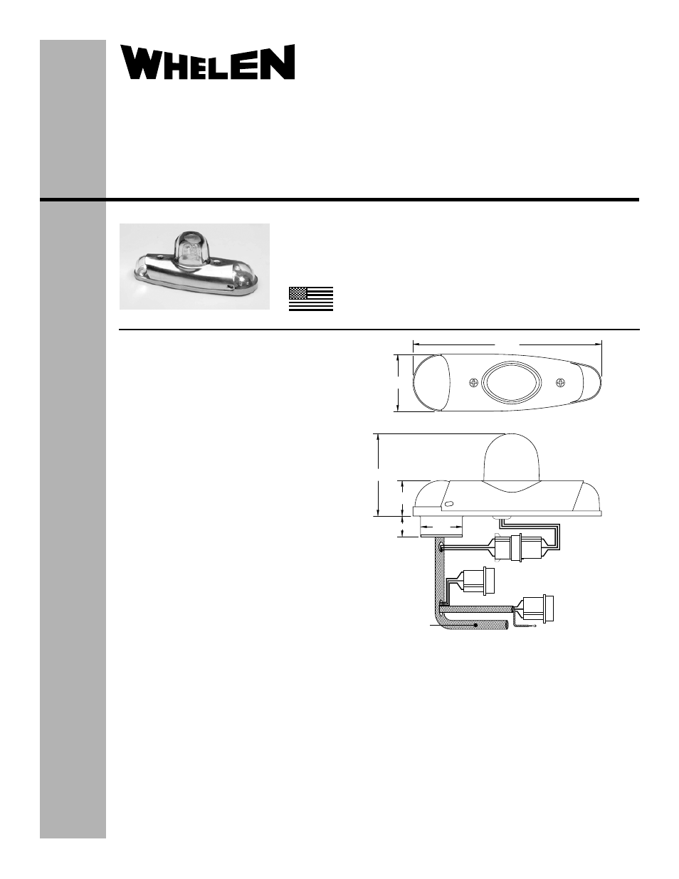
5.69
1.87
2.46
1.08
.618 MIN
1.25
POS 3 - WHITE (TRIGGER)
POS 2 - BLACK (CATHODE)
POS 1 - RED (ANODE)
RF Shield
POS -
POS 2 -
POS -
3 CASE GROUND
WHITE (+28VDC)
1 BLACK (-) GROUND
J1
1
2
3
J2
1
2
3
Lightning
Grounding
Braid
The conditions and tests required for TSO approval of this
article are minimum performance standards. It is the
responsibility of those installing this article either on or
within a specific type or class of aircraft to determine that
the aircraft installation conditions are within the TSO
standards. TSO articles must have separate approval for
installation in aircraft. The article may be installed only if
performed under 14 CFR part 43 or the applicable
airworthiness requirements.
®
ENGINEERING COMPANY INC.
51 Winthrop Road
Chester, Connecticut 06412-0684
Phone: (860) 526-9504
Fax: (860) 526-2009
Internet: www.whelen.com
Sales/Service e-mail: [email protected]
Aviation
Installation Guide: 90375( )-series
Models 9037501 - 9037504
P/N: 01-0790375-01 through -04
LED Position Light/Strobe Assembly
©2008 Whelen Engineering Company Inc.
Form No.14182A (073010)
TSO-C30c
TYPES I, II, III
APPROVED
POSITION LIGHT:
Operational Voltage:. . . . . . . . . . 28 VDC (nominal)
Input Current: . . . . . . . . . . . . . . . 0.25 Amps
EQUIPMENT LIMITATIONS: An approved lighting
system consists of two lights, one located on each
wingtip. The baseplate must be mounted parallel to the
vertical and horizontal centerlines of the aircraft to project
the patterns properly. The strobe tube assembly must be
connected to a strobe power supply, such as Whelen
model 70888, 70879 or other approved models.
CONTINUED AIRWORTHINESS: The 90375 series
LED wingtip position light assembly is designed with 3
forward LED’s and two aft LED’s. If any one LED fails,
the unit must be repaired or replaced. Inspect the lens.
Replace if there is excessive scratching, discoloration or
cracking.
INSTALLATION PROCEDURES: The following
information is to assist in the installation of a Whelen
90375 Light System.
1.
Choose the appropriate 90375( ) series
replacement light assembly.
2.
The installation procedure described in the following
text will be confined to a single light installation, but
is identical for multiple light installations.
3.
Make sure the existing system is equipped with an
appropriate sized breaker. Connect the Position
Light (J1) to existing mating 28VDC connector
(Whelen model #A442).
4.
Connect the Air Frame ground to the case ground.
5.
Connect the strobe, J2, to the strobe power supply
as shown in the figure. It is recommended that the
RF shield be connected to the strobe power supply
chassis and the lightning grounding braid be
connected to the Air Frame ground.
6.
Remove the retainer from the light assembly.
7.
Position the base of the new light assembly onto the
mounting surface. Insert three (3) #6-32 pan head
screws into the mounting holes (clearing the wires) and
tighten firmly. Reinstall the forward position lens so that the
two notches are positioned under the shroud, with each notch
equidistant to the centerline of the retainer mounting post.
8.
Reinstall lenses and retainer so as to clear the two internal
wires.
9.
Check all avionics systems for interference from the
installation.
10. A flight check should be performed by a properly certified
pilot.
11. Update aircraft records, complete Form 337 and obtain FAA
field approval for installation, as required.
TSO-C96a
CLASS II
APPROVED
MADE IN THE U.S.A.