Whelen 7114800 User Manual
Aviation, Wing, Engineering company inc
Page 1
®
ENGINEERING COMPANY, INC.
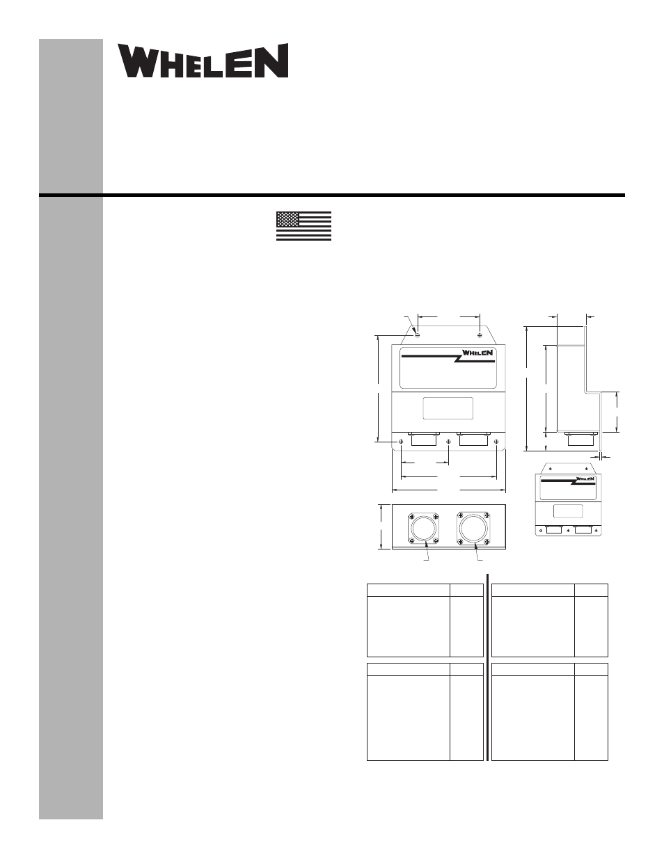
MS3470L16-8P
1.80
4.56
.080
.75
3.50
5.00
1.20
1.63
5XØ.156
THRU
3.830
1.915
4.270
2.500
J1
WING
J2
CHESTER, CONNECTICUT 06412-0684
BY:
MODEL 7114800
INPUT
OUTPUT
®
ENGINEERING COMPANY, INC.
J1
TAIL
J2
CHESTER, CONNECTICUT 06412-0684
BY:
MODEL 7114801
INPUT
OUTPUT
MS3470L18-11S
7114801 Shown
for reference only
ANTI-COLL
ANTI-COLL
ANTI-COLL
POSITION
POSITION
GROUND REF.
GROUND REF.
NO CONNECTION
ANTI-COLL
ANTI-COLL
ANTI-COLL
POSITION
POSITION
NO CONNECTION
NO CONNECTION
NO CONNECTION
ANTI-COLL
ANTI-COLL
ANTI-COLL
ANTI-COLL
ANTI-COLL
POSITION 1
POSITION 1
POSITION 2
POSITION 2
GROUND REF.
GROUND REF.
ANTI-COLL
ANTI-COLL
ANTI-COLL
ANTI-COLL
ANTI-COLL
ANTI-COLL
POSITION
POSITION
NO CONNECTION
NO CONNECTION
NO CONNECTION
28V
GND
SYNC.
S8V
GND
28V
GND
28V
GND
SYNC.
S8V
GND
ANODE
CATH. 1
CATH. 2
CATH. 3
CATH. 4
ANODE
CATH.
ANODE
CATH.
28V
GND
ANODE
CATH. 1
CATH. 2
CATH. 3
CATH. 4
CATH. 5
ANODE
CATH.
A
B
C
D
E
F
G
H
A
B
C
D
E
F
G
H
A
B
C
F
G
D
E
J
K
H
L
G
A
B
C
D
E
H
J
F
K
L
J1 SIGNAL
J1 SIGNAL
Model 7114800
Model 7114801
J2 SIGNAL
J2 SIGNAL
CONTACT
CONTACT
CONTACT
CONTACT
®
ENGINEERING COMPANY INC.
Route 145, Winthrop Road,
Chester, Connecticut 06412
Phone: (860) 526-9504
Fax: (860) 526-2009
Internet: www.whelen.com
Sales/Service e-mail: [email protected]
Aviation
Installation Guide:
Aviation model(s) 7114800, 7114801
P/N: 01-0771148-00
01-0771148-01
Flasher/Current Source Ass’y
©2009 Whelen Engineering Company Inc.
Form No.14297A (031414)
SPECIFICATIONS:
Nominal Operational Voltage: ...................................... 28 VDC
Current Source Input Current:
LED Forward Position Light ...................................... 0.35 AMPS (each)
LED Tail Navigation Light .......................................... 0.25 AMPS
LED Wing Anti-Collision Light ([email protected] Sec.)..... 4.0 AMPS
LED Wing Anti-Collision Light (Avg.) ....................... 0.75 AMPS
LED Tail Anti-Collision Light ([email protected] Sec.) ....... 3.8 AMPS
LED Tail Anti-Collision Light (Avg.).......................... 0.71 AMPS
Flashrate......................................................................... 45 ±5 Per. Min.
Total Weight ................................................................... 0.75 lbs.
EQUIPMENT LIMITATIONS:
An approved forward anti-collision/position light system consists of at
least 2 flasher/current source units, each connected to a LED anti-
collision lighthead, model 71184( ), and an LED position lighthead,
models 7118201 (green) and 7118202 (red).
An approved tail anti-collision/navigation light system consists of at
least one flasher/current source unit, connected to an LED anti-
collision and tail navigation lighthead, model 90354( ).
Certain types of installations may require additional testing.
CONTINUED AIRWORTHINESS:
The forward position light is designed with 6 LED’s. The forward anti-
collision light is designed with 24 LED’s. The tail navigation light is
designed with 4 LED’s. The tail Anti-Collision light is designed with 30
LED’s. If any bank of LEDs fail, the lighthead module should be
checked. If the module checks good, replace the flasher.
NOTE: To reduce eye strain use an optical filter such as dark glasses
or a blue covering dome during LED inspection.
Note: The anti-collision light will automatically shut-off after 9-10
flashes if a failure is detected.
INSTALLATION PROCEDURES:
1.
Consider areas or locations designated by the aircraft
manufacturer. Check that breakers are properly rated.
2.
Attach the flasher using the (5) 0.156 dia. mounting holes.
3.
Connect the anti-collision light inputs, position light inputs, and
navigation light inputs according to the charts shown. Connect
the cable harnesses from 7118201/7118202, and 71184( ) to
7114800 and connect the cable harnesses from 9035401 to
7114801. Connections to be in accordance with FAA approved
methods.
4.
Check all avionic systems for interference from the installation
5.
A flight check should be performed by a certified pilot
6.
Update aircraft records, complete form 337 and obtain FAA field
approval for installation, as necessary
MADE IN THE U.S.A.
The conditions and tests required for TSO approval of this article are
minimum performance standards. It is the responsibility of those
installing this article either on or within a specific type or class of
aircraft to determine that the aircraft installation conditions are within
the TSO standards. TSO articles must have separate approval for
installation in aircraft. The article may be installed only if performed
under 14 CFR part 43 or the applicable airworthiness requirements.
TSO-C30c
TYPES I, II & III /
TSO-C96a
CLASS II
APPROVED