Whelen MicroBurst Series User Manual
Microburst™ series lighting, Engineering company inc
Page 1
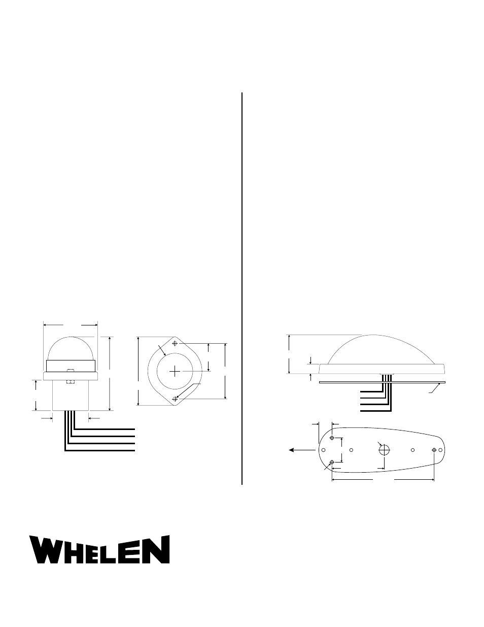
Wire Length = 8"
Gasket
1.41"
.35"
Black (Ground)
Red (+14V) - NAV.
Orange (+14V) - LED Strobe
Yellow (SYNC)
.125" Dia.
#4-40 MTG.
.48"
Ø.370"
.890"
1.915"
3.740"
Forward
1.71"
2.32"
1.125"
Black (Ground)
Wire Length = 8"
Red (+14V) - NAV.
Orange (+14V) - LED Strobe
Yellow (SYNC)
(.96")
Ш.125"
Ш1.13"
2.16"
1.75"
.875"
®
ENGINEERING COMPANY INC.
51 Winthrop Road
Chester, Connecticut 06412-0684
Phone: (860) 526-9504
Fax: (860) 526-2009
Internet: www.whelen.com
Sales/Service e-mail: [email protected]
MicroBurst™ Series Lighting
©2010 Whelen Engineering Company Inc.
Form No.14360B (092811)
LED Wingtip and Tail Lighting for Experimental and Light Sport Aircraft
MicroBurst I Installation...
1.
Drill two #4-40 mounting holes per suggested mounting pattern.
2.
Connect the wires using the wire chart. All leads must be
connected by FAA approved techniques using approved
hardware.
3.
Make sure the existing system is equipped with an appropriate
sized breaker.
4.
Remove two #4-40 screws from the MicroBurst taillight
assembly.
5.
Install the light assembly and insure that all leads are clear of any
obstructions and ty-wrap as required.
6.
Remount the lens and retainer onto the assembly. Attach the
lens and retainer with two #4-40 screws. Secure light assembly
using approved vibration resistant mardware methods.
SPECIFICATIONS:
Nominal Operational Voltage: ..........................14 VDC
Typical Input Current:
LED Strobe Light (Average): .............................. 0.15 Amps
LED Strobe Light (Pulse):................................... 0.80 Amps
LED Strobe Light Flashrate: ............................... 45± 5 per min.
Tail Navigation Light: .......................................... 0.2 Amps
Total Weight:....................................................... 0.15 lbs.
Replacement Lens P/N 68-3970991-30
MicroBurst II & III Installation...
1.
Drill three #4-40 mounting holes per suggested mounting
pattern.
2.
Connect the wires using the wire chart. All leads must be
connected by FAA approved techniques using approved
hardware.
3.
Make sure the existing system is equipped with an appropriate
sized breaker.
4.
Remove two #4-40 screws from the MicroBurst wingtip light
assembly to remove the lens retainers. Save these screws.
Remove the lens and locate the three mounting holes.
5.
Install the light assembly with gasket and insure that all leads are
clear of any obstructions and ty-wrap as required. Secure light
assembly using approved vibration resistant mardware methods.
6.
Remount the lens and retainers onto the assembly. Attach the
lens and retainer with the two saved screws.
SPECIFICATIONS:
MicroBurst II
MicroBurst III
Nominal Operational Voltage:
14 VDC
14VDC
Typical Input Current:
LED Forward Nav Light: ..................... 0.2 Amps
0.25 Amps
LED Strobe Light (Average)................ 0.2 Amps
0.2 Amps
LED Strobe Light (Pulse): ................... 1.20 Amps
1.20 Amps
LED Strobe Light Flashrate: ............... 45± 5 /min.
45± 5 /min.
Total Weight: ....................................... 0.2 lbs.
0.21 lbs.
Replacement Lens P/N 68-3971132A30
Not To Scale
NOTE: Connecting the SYNC (Yellow) wires together will cause those lights to flash
at the same time. If synchronization is not necessary or desired, the connection
may be left open.
Product does not meet the requirements of 91.205(c), required equipment for night flight.
Airplanes certified for night operation should not consider this product.