Whelen 7108019 User Manual
Aviation
Page 1
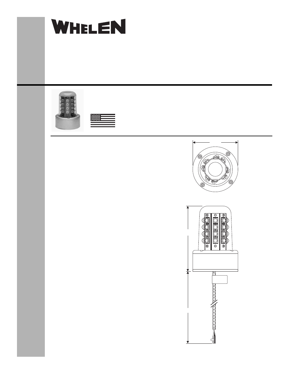
2.60"
3.74"
12"± 1"
White 18 AWG - (+) 28VDC
Black 18 AWG - (-) Ground
®
ENGINEERING COMPANY INC.
51 Winthrop Road
Chester, Connecticut 06412-0684
Phone: (860) 526-9504
Fax: (860) 526-2009
Internet: www.whelen.com
Sales/Service e-mail: [email protected]
Aviation
Installation Guide:
Model 71080( )-series
Model(s) 7108019
P/N:01-0771080-19
LED Anti-Collision
Light Assembly
©2011 Whelen Engineering Company Inc.
Form No.14500B (090612)
OPERATING INSTRUCTIONS:
Operational Voltage: . . . . . . . . . . . . . . . . . . . . . 28 VDC nominal
(Operation from 22-30 VDC)
Average Input Current: . . . . . . . . . . . . . . . . . . . 0.67 Amps
Pulse @ 0.3 Sec.: . . . . . . . . . . . . . . . . . . . . . . . . 3.0 Amps
Flashrate: . . . . . . . . . . . . . . . . . . . . . . . . . . . . . . 45± 5 per
EQUIPMENT LIMITATIONS: An approved Anti-Collision light assembly should
be located so that their light will not impair the crews vision or detract from the
conspicuity of the position lights. The light should be mounted on a thermally
conductive surface. The baseplate must be mounted parallel to the vertical and
horizontal centerlines of the aircraft to project the patterns properly.
Certain types of aircraft may require additional testing.
CONTINUED AIRWORTHINESS: The 71080 series LED anti-collision light
assembly is designed with 8 vertical columns consisting of 4 LEDs each.
Should any one LED fail, the unit must be repaired or replaced. Note: To
reduce eye strain use an optical filter such as dark glasses or a blue covering
dome during LED inspection.
Inspect the lens and replace if there is excessive scratching, pitting,
discoloration or cracking.
INSTALLATION PROCEDURES: The following information is to assist in the
installation of a Whelen LED Anti-collision Light System.
1.
Using the mounting detail information provided, prepare the aircraft for
means to secure the LED Light assembly.
2.
Carefully remove the lens retainer and lens from the assembly.
CAUTION! Do not touch the LED lens surface with either fingers or sharp
objects. This could soil and/or damage the lens and effect the optical
performance of the LEDs.
3.
Connect the light inputs according to the chart shown. Connect the power
lead to an appropriately sized breaker. Connections to be in accordance
with FAA approved methods.
4.
Secure the adaptor plate to the aircraft using vibration resistant threaded
fasteners. Flat head, #8 screws are recommended.
5.
Install the light assembly and insure that all leads are clear of any
obstructions. Secure leads as required.
CAUTION: Do not over-torque
screws (item 6) when reinstalling the light assembly onto the adapter
plate.
6.
Reinstall the lens and confirm proper gasket fit.
7.
Install lens retainer. Using appropriate hardware, secure as required.
8.
Check all avionics systems for interference from this installation.
9.
A flight check should be performed by a properly certified pilot.
10. Update aircraft records, complete Form 337 and obtain FAA field approval
for installation.
TSO-C96a
CLASS I & III
APPROVED
MADE IN THE U.S.A.
The conditions and tests required for TSO approval of this
article are minimum performance standards. It is the
responsibility of those installing this article either on or
within a specific type or class of aircraft to determine that
the aircraft installation conditions are within the TSO
standards. TSO articles must have separate approval for
installation in aircraft. The article may be installed only if
performed under 14 CFR part 43 or the applicable
airworthiness requirements.