DE DIETRICH DHD585XE1 User Manual
Page 10
Discharge mode
DHD585XE1
attach the extensions (Fig.4 Det.A) to the upper plate (Fig.4) with the supplied screws. Position
the upper plate (Fig.4.1) on the ceiling, drill four 8mm holes corresponding to the drill jig.
Insert the expander sleeves into the holes (Fig, 4-1 – A) and attach the plate to the ceiling with
the screws (Fig. 4-1-B).
Then attach the lower structure (Fig, 6.2) to the hood lining up its holes with the bolts welded
to the ventilator support (Fig. 6.1). Insert the supplied washers and nuts (Fig. 6.2-A) tightening
them with an appropriate tool.
Connect the air discharge conduit to the motor unit by way of the collar. Insert the upper
structure (fig. 6.3) on the lower structure while adjusting the position to the desired height,
respecting the minimum required height between the cooker and the hood. Tighten the screws
on the two structures (Fig. 6.3 B).
Then lift the hood with the structure and the conduits already inserted until the four springs
(Fig. 6.6 –E) hook onto the drill jig (Fig. 6.3C). Once the two parts are hooked together, tighten
the two parts (Fig. 5.1, Fig. 5.2, Fig. 11) with the safety screws (Fig. 5.2A).
Connect the hood conduit to the air discharge hole.
Then insert the two telescopic pipes (fig. 6.4 e 6.5) into the lower part of the hood (Fig. 12).
Before inserting the telescopic pipes completely (Fig, 6.4 e 6.5) hook up the display connection
(Fig. 13). Then lift the conduit completely and attach it to the hood with the supplied screws
(Fig. 12-A). Raise the upper conduit to the ceiling and attach it with the screws (Fig. 6.6 –D).
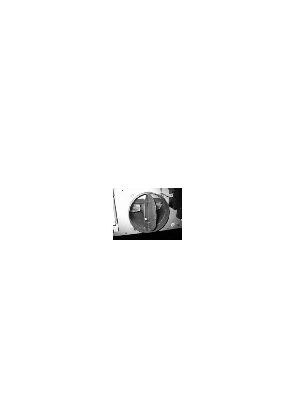
Check valve blockage
Warning: Before connecting the air exhaust hose, make sure that the check valves are free to
turn over freely.
In filtering application that the stop valve doesn’t permit the entrance of wind and exhau-
sted air.
Recirculation Mode
To install the unit in the recirculation mode, attach the air deflector (Fig. 4.2) to the upper flange
(Fig. 4.3) with the four supplied screws (Fig. 4.3-A).
Then proceed with the installation as indicated for the discharge mode. You must insert a shea-
th between the deflector and the motor discharge.
-REMOVAL OF THE FILTER CARTRIDGE (Fig. 3A)
-MOUNTING THE CARBON FILTER (FIG. 9Z)
1. Remove the cartridges.
2. Position the carbon filter on the cartridge inside the hood.
3. Position the two containment flanges.
4. Repeat the operation for all of the cartridges.
32