Appendix: voltage and current harmonics, Theory, See chapter 0 fo – Amprobe ACD-51HP Power-Quality-Clamp-Ons User Manual
Page 35: T sin( v v v(t)
ACD-51HP - ACD-56HPQ
8. APPENDIX: VOLTAGE AND CURRENT HARMONICS
8.1. THEORY
Any periodical non-sine wave can be represented as a sum of sinusoidal waveforms each
having a frequency that corresponds to an integer multiple of the fundamental frequency,
according to the relation:
)
t
sin(
V
V
v(t)
k
k
1
k
k
0
ϕ
ω
+
+
=
∑
∞
=
(1)
where:
V
0
= Average value of v(t)
V
1
= Amplitude of the fundamental of v(t)
V
k
= Amplitude of the k
th
harmonic of v(t)
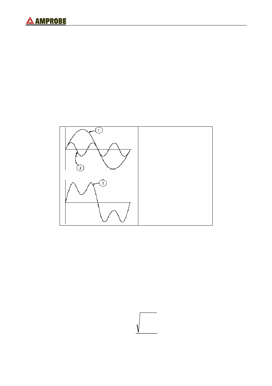
LEGENDA:
1. Fundamental
2. Third Harmonic
3. Distorted waveform sum of two
previous components.
Effect of the sum of 2 multiple frequencies.
In the mains voltage, the fundamental has a frequency of 60 Hz, the second harmonic has
a frequency of 120 Hz, the third harmonic has a frequency of 180 Hz and so on. Harmonic
distortion is a constant problem and should not be confused with short durations events
such as sags, surges or spikes.
It can be noted that in (1) the index of sigma is from 1 to the infinity. What happens in
reality is that a signal does not have an unlimited number of harmonics: a number always
exists after which the harmonics value is negligible. The EN 50160 standard recommends
the index end in (2) in correspondence of the 40
th
harmonic.
A fundamental element to detect the presence of harmonics is THD defined as:
1
40
2
2
V
V
THDv
h
h
∑
=
=
This index takes all the harmonics into account. The larger it is, the more distorted the
waveform gets.
EN - 31