Amprobe A-5000 Sheath Fault Locator User Manual
Page 18
16
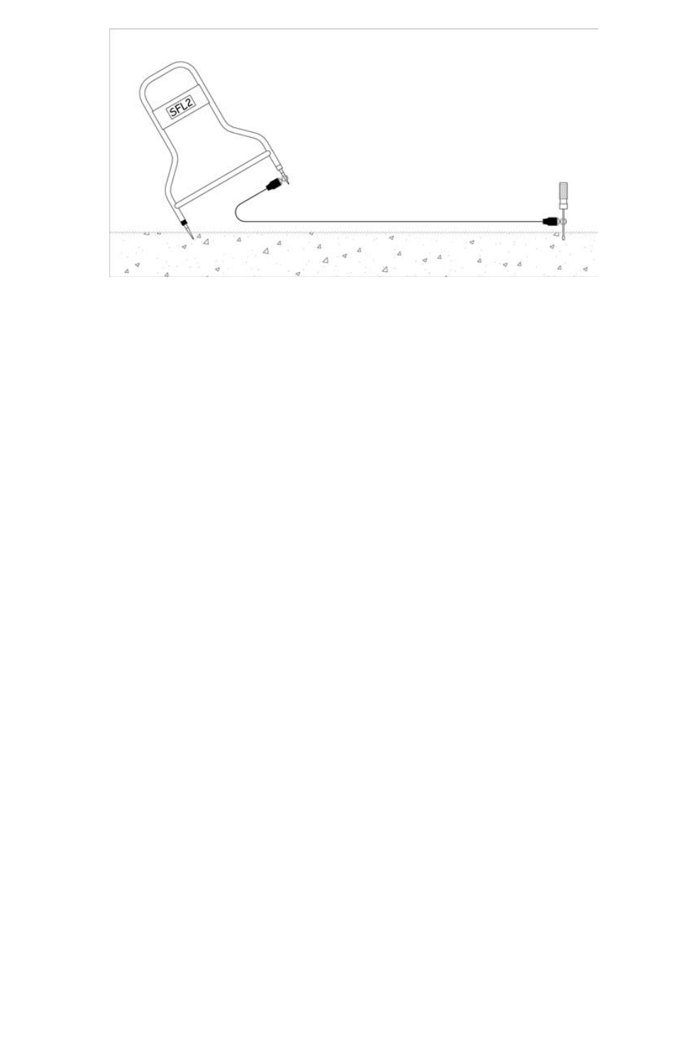
Figure 8-4: Fault Location Using Extension Cable for Increased Sensitivity
high And Low Impedance Faults
Before beginning a fault search it is a good idea to know the severity of the fault. This is measured in terms of its resistance
or impedance to ground. Faults where the ground is wet and/or a very large piece of the insulation is missing are found at the
low end of the range (<500 Ohms). Conditions where the ground is very dry and/or the actual fault is a small pinhole where the
conductor has a very small ground contact area are found at the high end of the fault range (>1-3 MΩ).
A low impedance fault is the easiest to find since there is more signal to detect.
Generally, the more bars and a higher number displayed at synchronization, the larger the fault.
A high impedance fault is more difficult to locate. Characteristically, the A-5000 Receiver may not detect the signal after moving
a short distance away from the ground point. The higher the impedance of the fault, the closer you must be to detect it.
Example
If the A-Frame only reliably points away from the ground connection within 20’ (3 m), then the A-frame will only detect the
fault within about 20’ (3 m). Outside this distance the signal is too weak to reliably detect.
For this reason we highly recommend tracing and marking the line before searching out high impedance faults.
multiple Faults
Locating multiple faults is the most difficult and confusing fault situation. It is especially important in this case to accurately
trace the faulty conductor before beginning the fault search. Stay exactly above the line if possible and verify each suspected
fault by monitoring the active number to see which fault has the higher number. Remember that a very strong or low
impedance fault will mask the detection of a weak or high impedance fault. The safest and best way to find multiple faults is to
repair each fault as it is positively identified and then continue the search. See Figure 5-3.
mAINtENANCE
A-5000 Receiver Battery Replacement.
Loosen the two thumbscrews located on the underside of the Receiver housing. Gently pull out battery door. Be careful not
to pull on the battery wires. Remove battery from battery holder and disconnect battery. Reverse procedure for installing new
battery.